Step 6: Controller assembly
Solder the male headers to the ItsyBitsy; for ItsyBitsy M4, only solder the headers along the two long sides of the board.
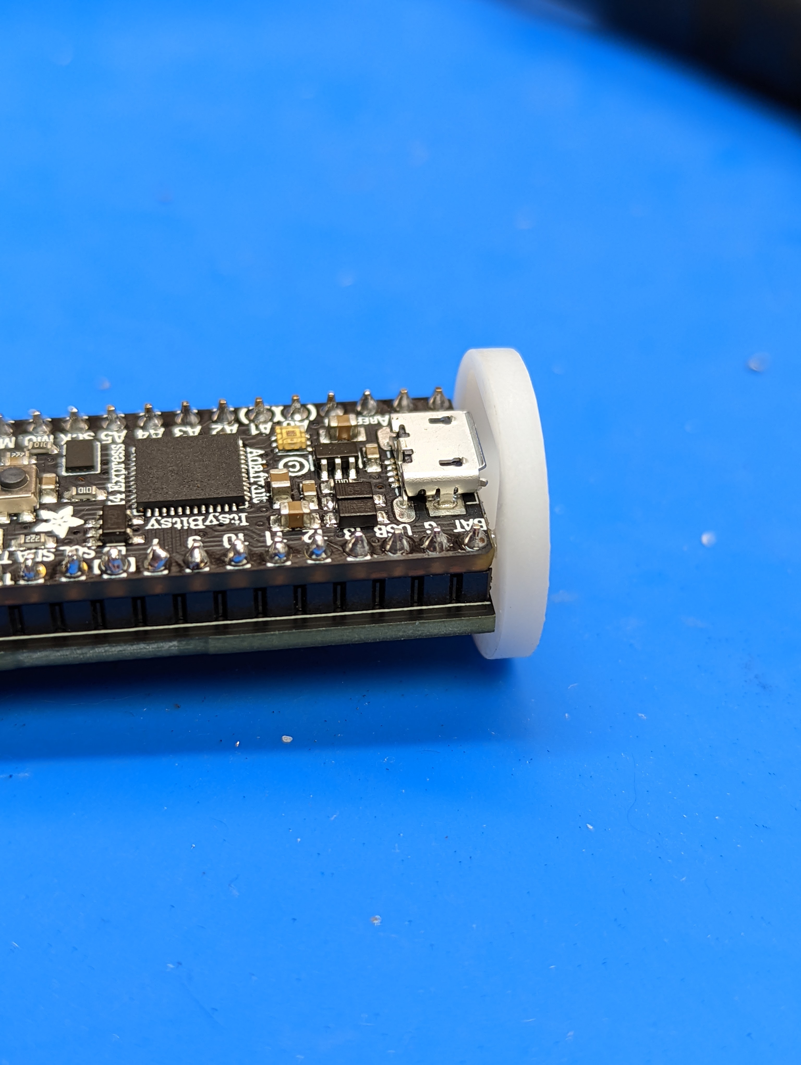
Solder the POV controller board to these headers underneath the Itsy Bitsy, forming a “sandwich” of two boards as shown in the photos below. Use flush cutters to trim the long pins of the headers so they are not in the way.


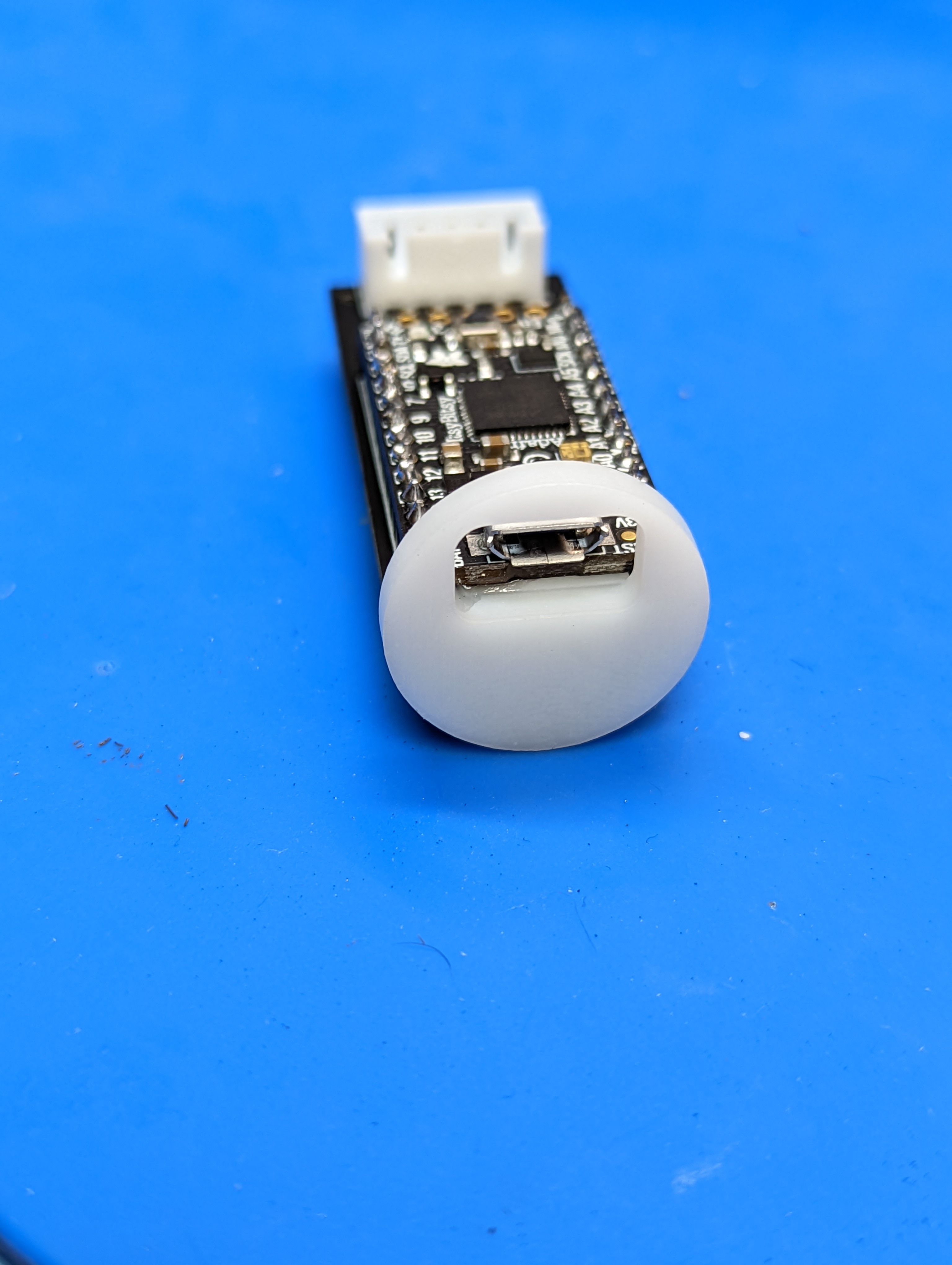
Insert the 3d printed controller cover between the two boards as shown below. Double-check that you can insert the USB cable into the ItsyBitsy through the opening in the 3d printed cover; if necessary, enlarge the opening using a file.
Use epoxy to glue the 3d printed cover to the controller. Be very careful that no epoxy gets on the USB connector of ItsyBitsy! Leave to dry.