Step 5: Controller wiring
Materials:
Controller wire harness (55cm, black, 5-wire)
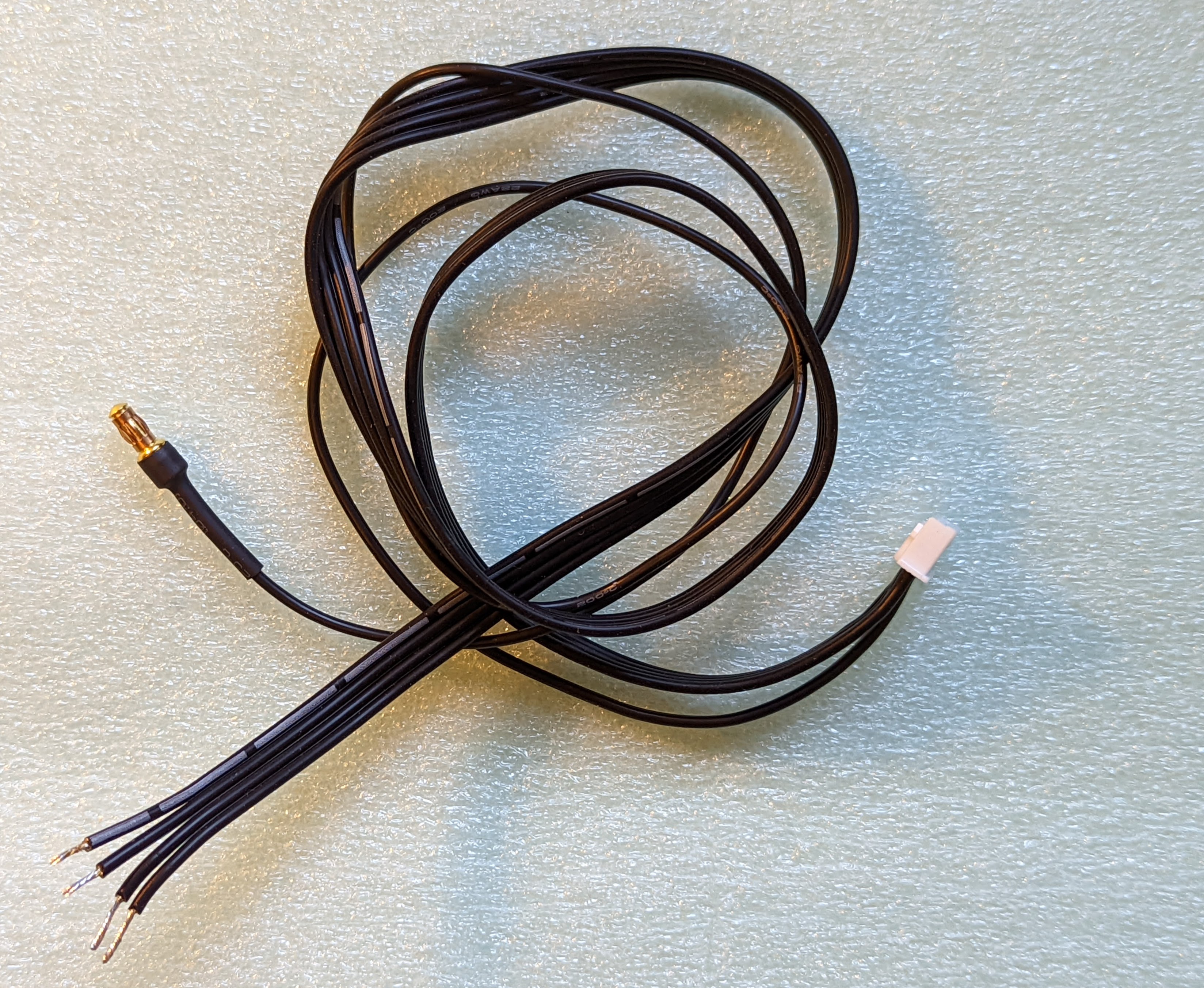
Before starting assembly, you need to match the wires of the wire harness to the contacts of the power distribution board. The wire harness contains 5 wires:
VCC (with white stripe)
Data
Clock
GND
BAT (with bullet connector)
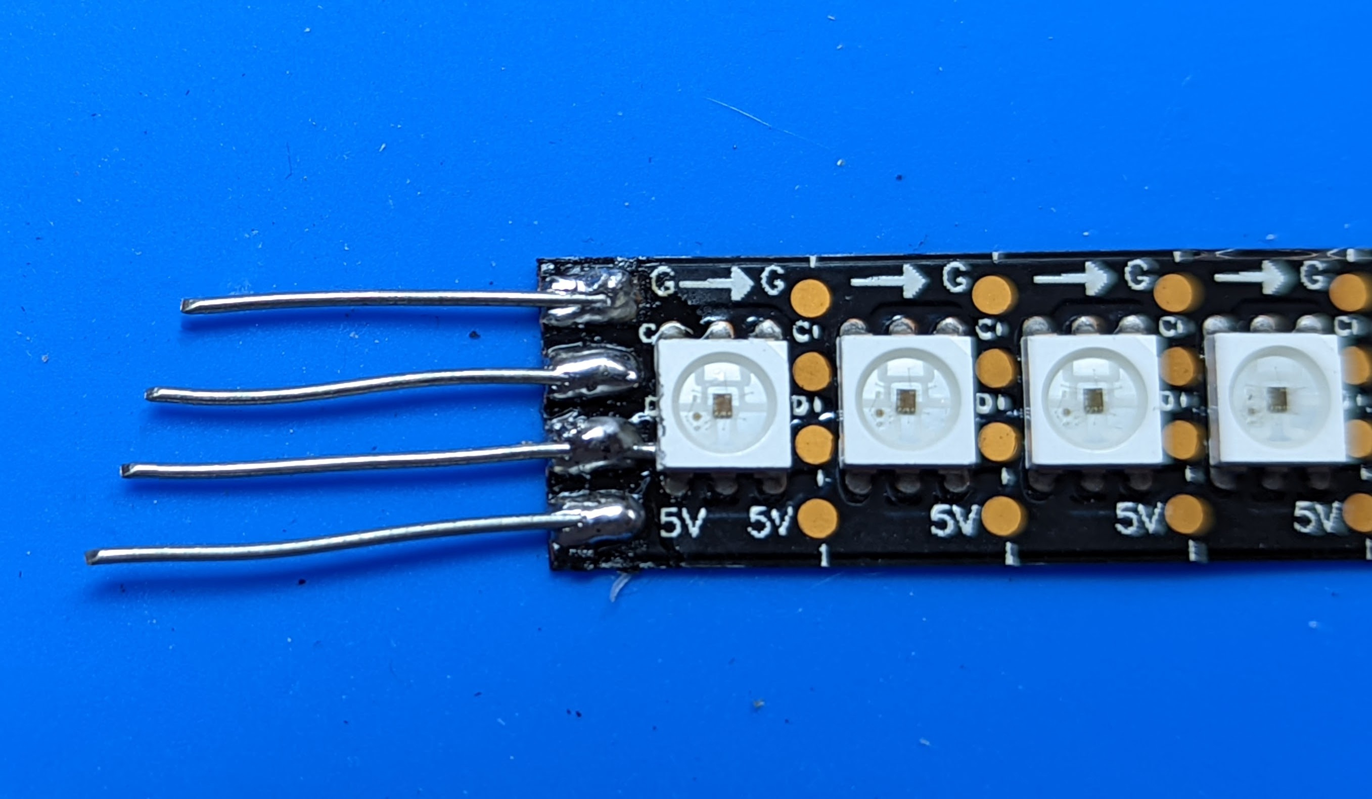
The first four wires will need to be soldered to the holes in PDB on the controller side of battery assembly. However, the match between the wires and the holes depends on the signal order on your LED strip (unfortunately, there is no standard).
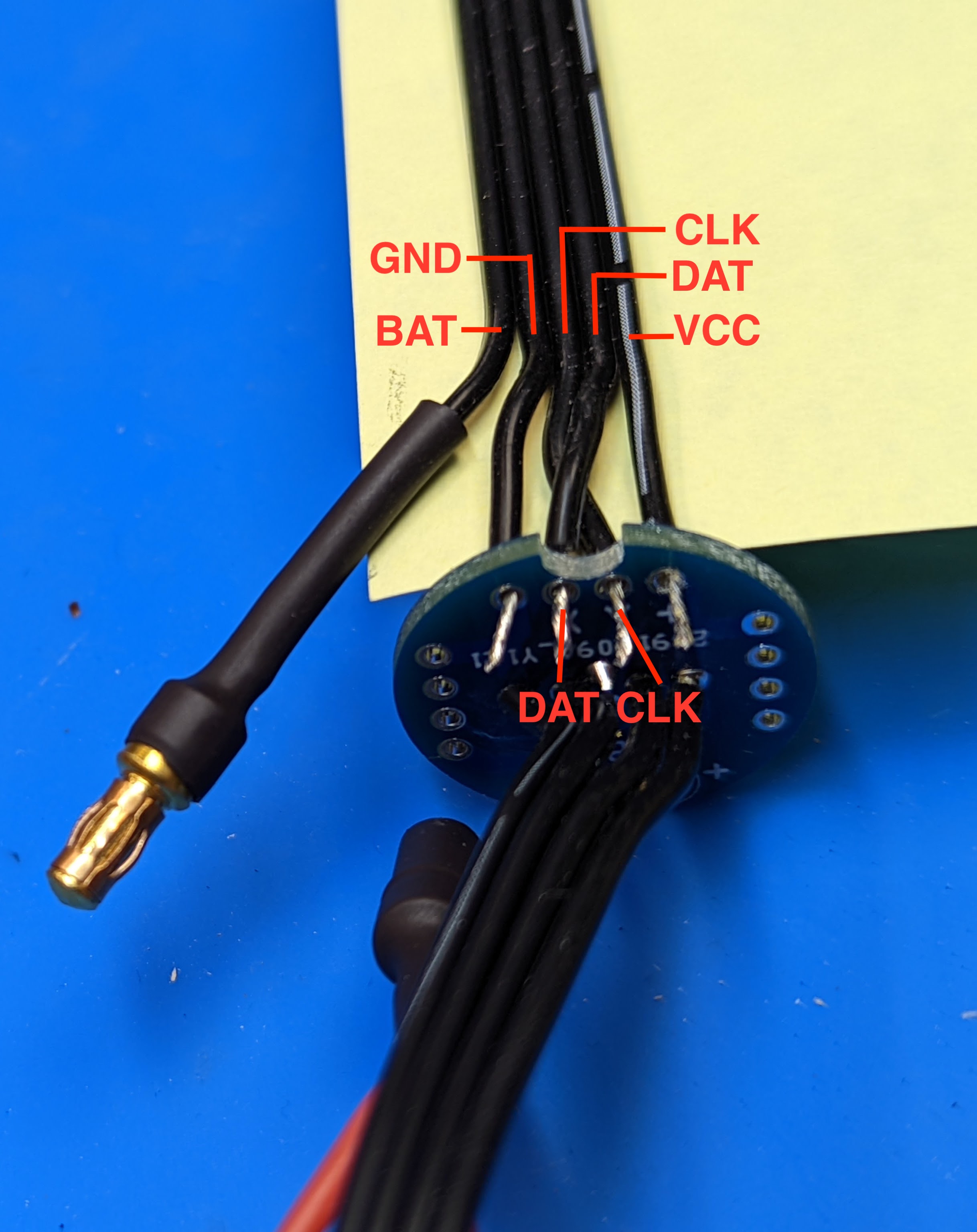
If the second from the top signal of your LED strip is Data (usually abbreviated D) and the third is Clock (C), connect the wires as shown in the photo below: VCC (white stripe) to the hole labeled +, and the other 3 wires into the next 3 holes in order.

(The yellow piece of paper in inserted between the wires and dowel to make it easier to see the wires in the photo. You do not need it for your build. )
If the second from the top is Clock and third is Data, as shown in the photo below
then connect the wires as shown in the photo below, crossing 2nd and 3rd wires (Clock and Data)
After inserting the wires into the holes of the PDB as described above, solder them. Trim the wires.
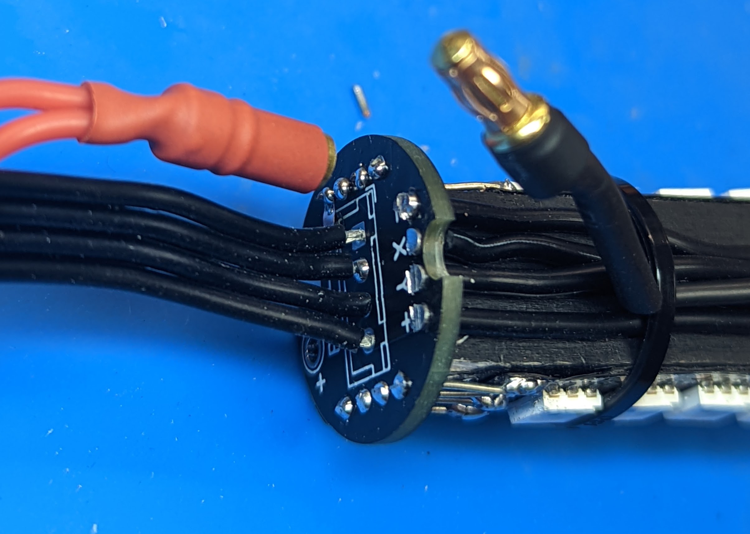
Feed the BAT wire through the cutout. Use zipties to fasten the wiring and LED strips to the dowel, similar to what you did with the other dowel.
Connect the bullet point connector at the end of BAT wire with the one coming from the battery assembly.
