Step 8: Testing
Before continuing, remove the USB cable from the controller. Make sure the switch is in middle (“off”) position.
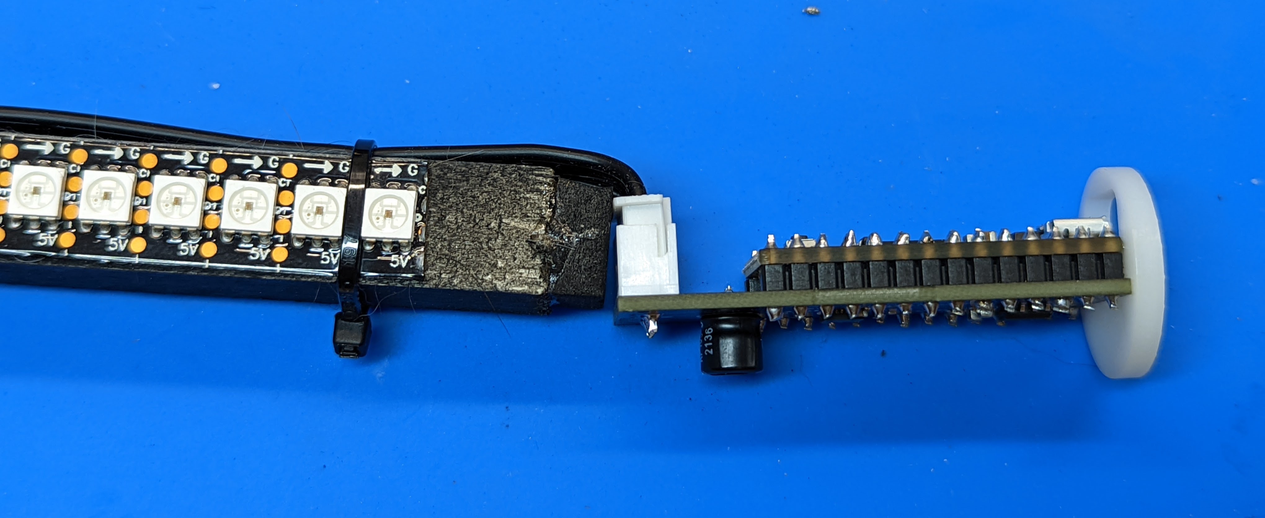
Plug the 5-pin JST connector into the POV controller as shown below.
By now, all electric connections are complete. Before inserting the assembled pieces into the tube, you need to test it. Turn the switch on (it is a 3-position switch; you will need to find out which of the 3 positions is “on”. The middle position is always “off” ). The staff must come to life, lighting up some LEDs to indicate the battery charge - the more LEDs, the higher the charge. If no LEDs come light up, either something is wrong with the wiring, or the batteries are completely discharged. In the latter case, you will need to charge the batteries as described in the user guide.
If everything worked OK so far, try twisting the controller between your fingers back and forth. You should see green and red lights travelling the length of the staff – the faster you move the controller, the quicker the lights should move. If this works, your staff is working as intended and you can move to the final assembly.