Step 3: Charge connector
Materials and tools:
Bag B from the kit
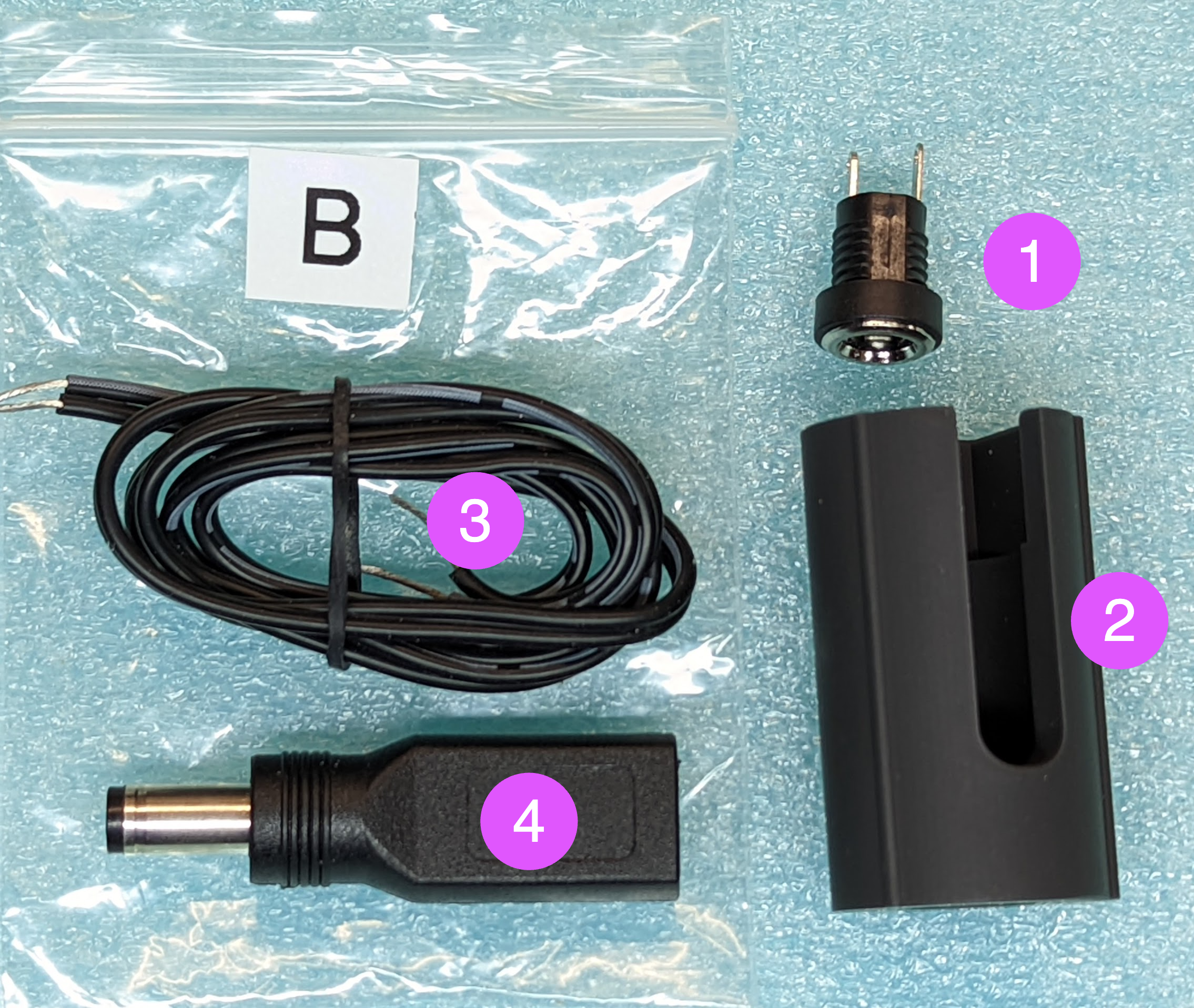
Charge connector
3d printed housing for charge connector
2-pin wire (55 cm, 24 AWG)
Charging adapter (USB C to 5.5mm barrel jack)
flush cutters, soldering iron
Steps:
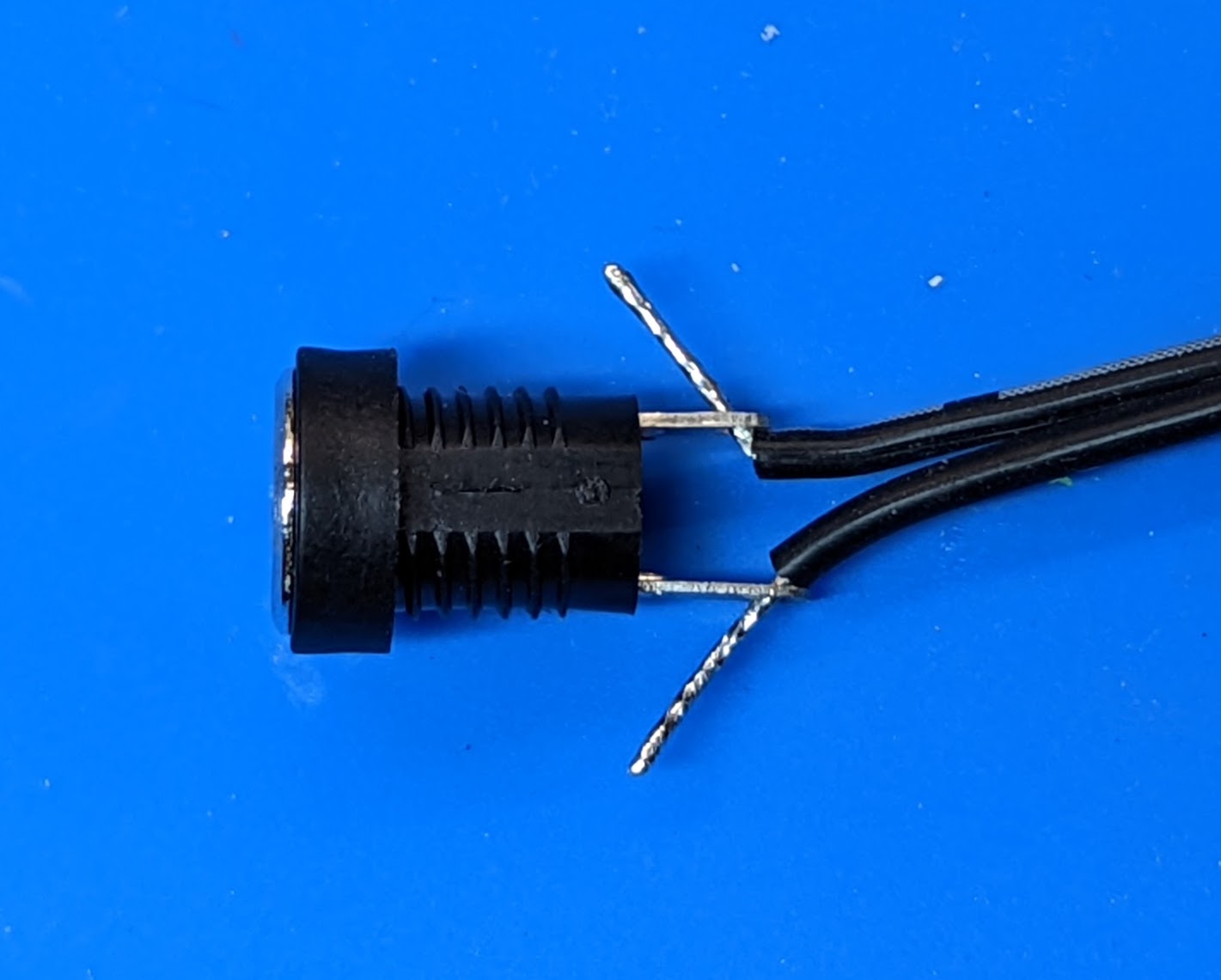
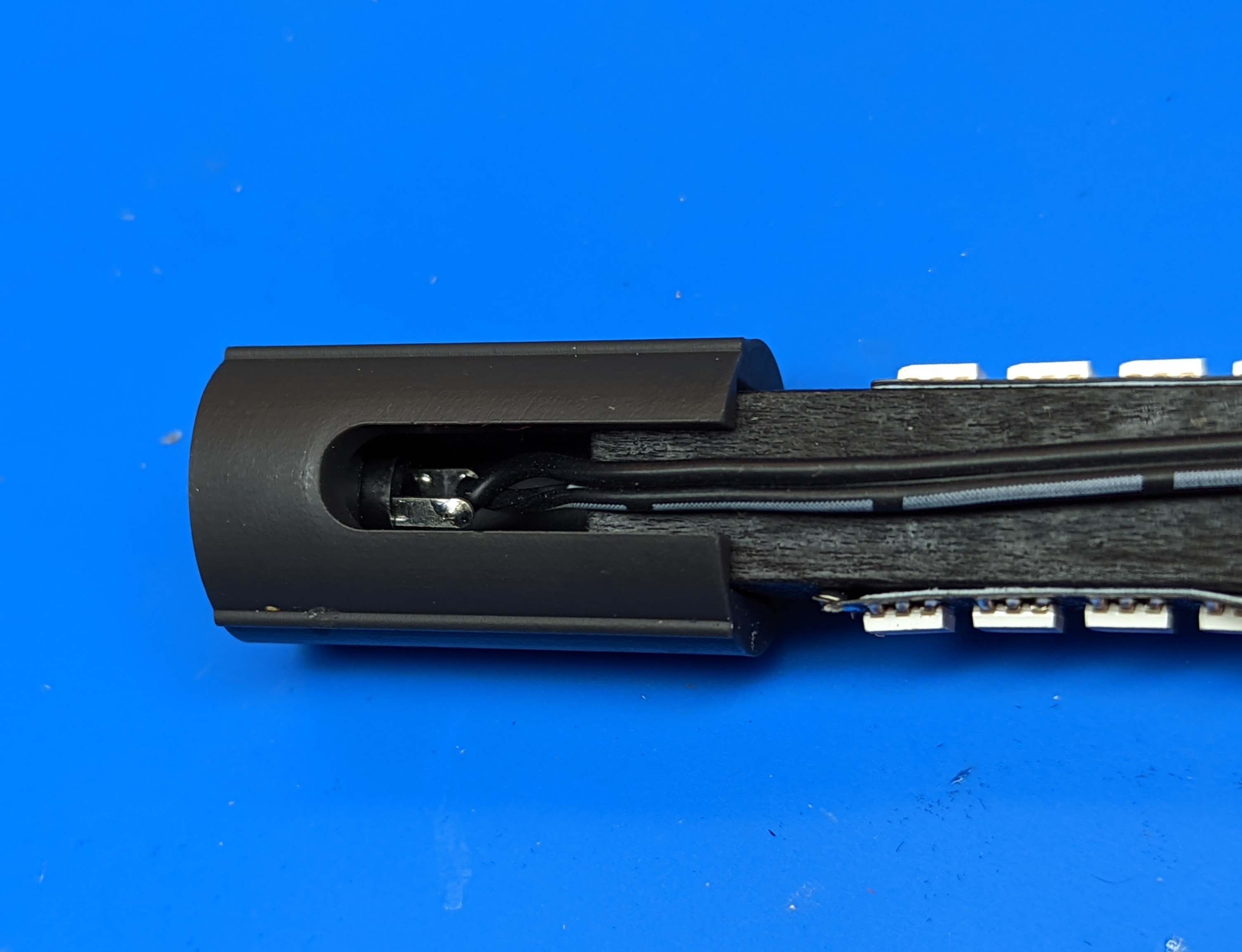
Take the two-pin wire from bag B. Insert the ends of the wire into holes in the charge connector contacts as shown below. Important: the wire with white stripe should be soldered to the shorter contact (this goes to the center pin, which is the positive contact).
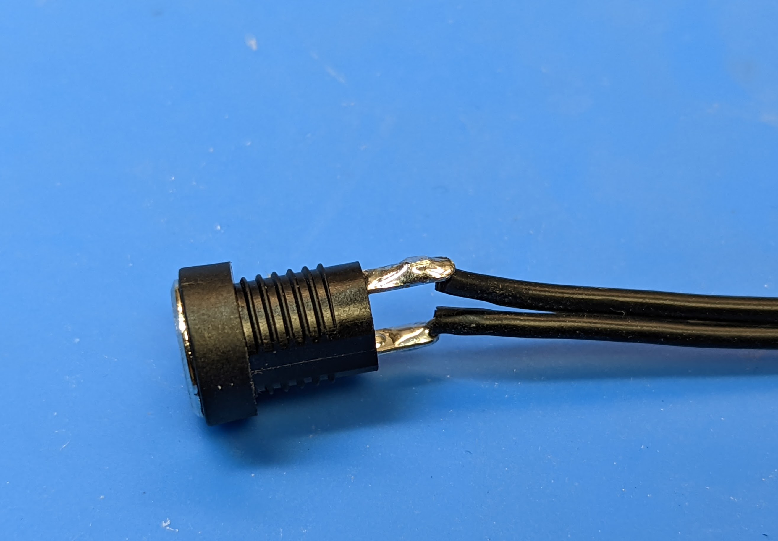
Solder the wires. Use flush cutters to trim the soldered wires.
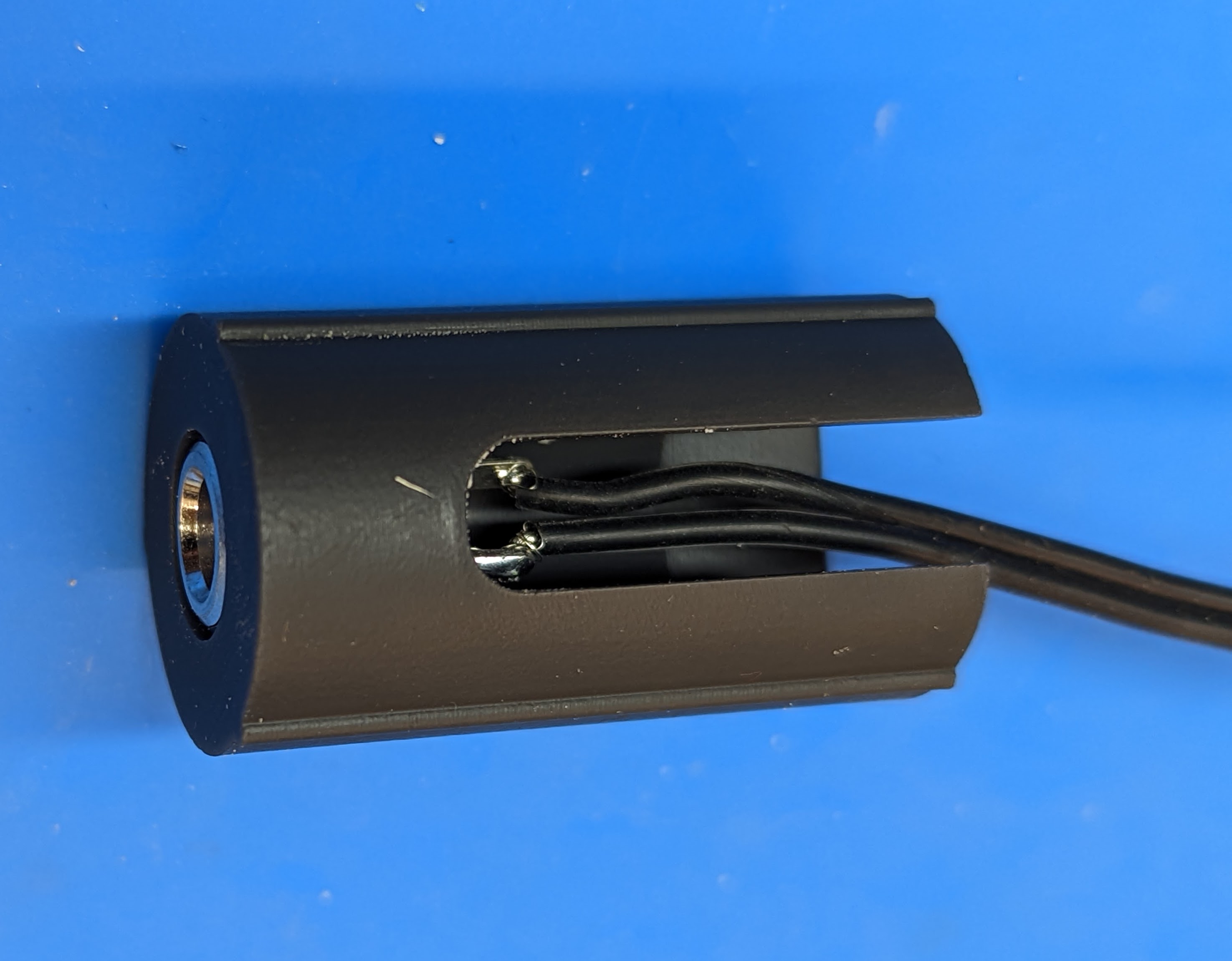
Insert the charge connector in the 3d printed spacer as shown below. Push against a flat surface (e.g. the table) to make sure it is all the way in.
Take the LED assemblies created previously. Select the one with PDB labeled “CHARGE” (blue PDB). Important: make sure you got the correct assembly! Put the 3d printed spacer with charge connector onto the other end of the dowel, making sure that the opening in the spacer is on the same side of the dowel as the two holes in the PDB.
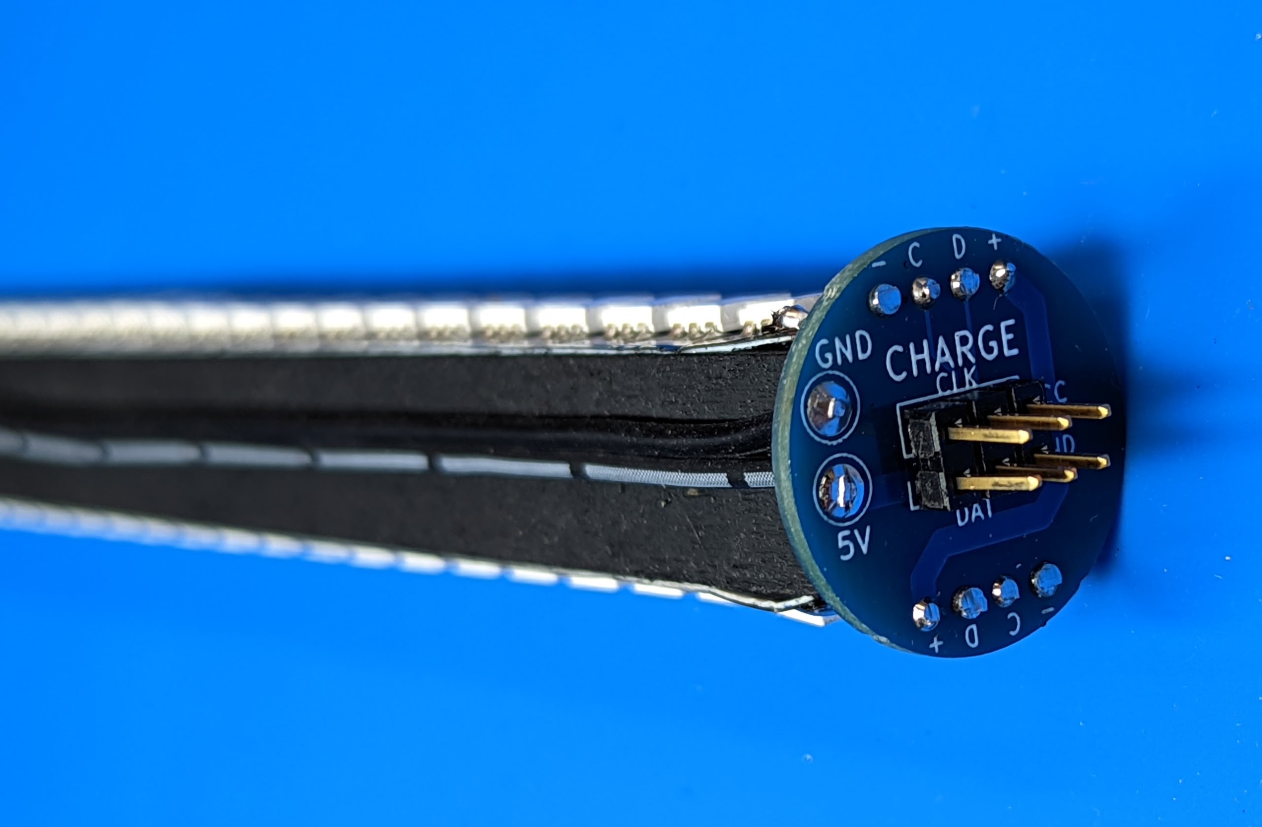
Run the wire along the wood dowel; straighten it to remove twists. Insert the tinned ends of the wire into the holes in the PDB. The wire with white stripe should go into the hole labeled “5V”. Solder the wire and then trim the wire ends protruding on the other side.
Bag B also contains the charge adapter - keep it to use when charging the staff.