Step 7: Controller assembly
Materials
Bag E from the kit
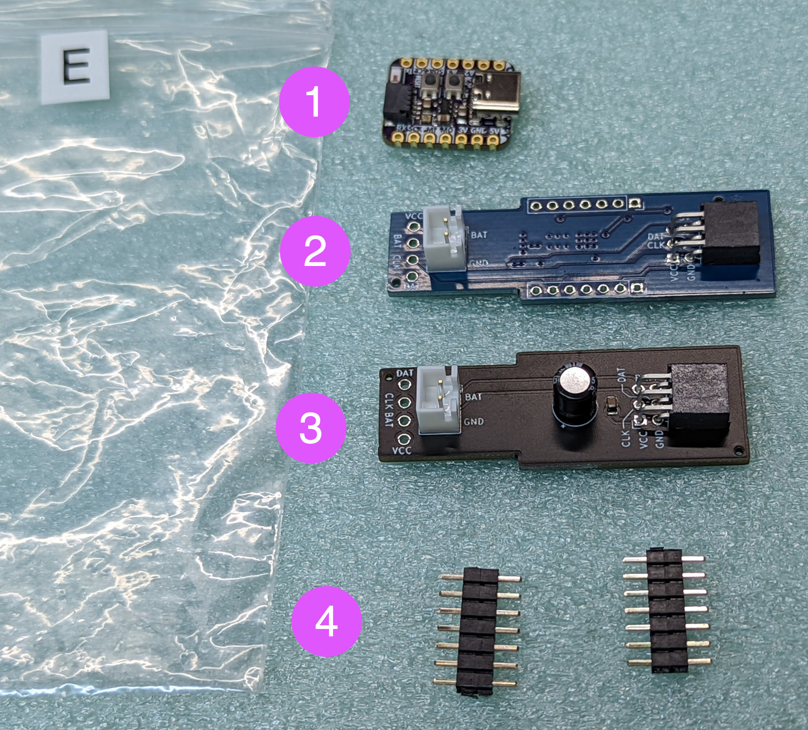
QT Py ESP32-S3 MCU, preprogrammed
Custom-made POV controller board (blue), containing Inertial Motion Unit, battery charge circuit, and more.
Switch connector board (black)
Two 7-pin headers
4-pin wire, left over from the previous step
Steps:
Before doing any work, get the ESP32-S2 Qt Py microcontroller from the bag and test it. To do that, connect it by USB cable to a computer or charger to power it up. The on-board NeoPixel LED should blink red, then yellow, then turn green. Wait for 20-30 seconds and open the WiFi connection dialog of your computer. You should see there a new WiFi network with the name POVSTAFFXXXX, where XXXX will be replaced by a 4-digit number, unique for each staff. Connect to this network; the password is in the information sheet which was included with your kit - if you misplaced it, email irobotics.store@gmail.com for help. Type the following address in the URL field of the browser: http://povstaff.local:8080 (note: the staff doesn’t support https protocol. If your browser gives you a warning about unsecure connection, click on “continue to site”.) You should see the webpage of the staff, which looks as follows:
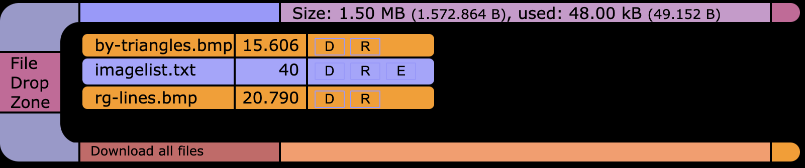
If you see the files imagelist.txt, rg-lines.bmp and bg-triangles.bmp, everything is good - you can disconnect the USB cable and proceed. Otherwise, check the troubleshooting section.
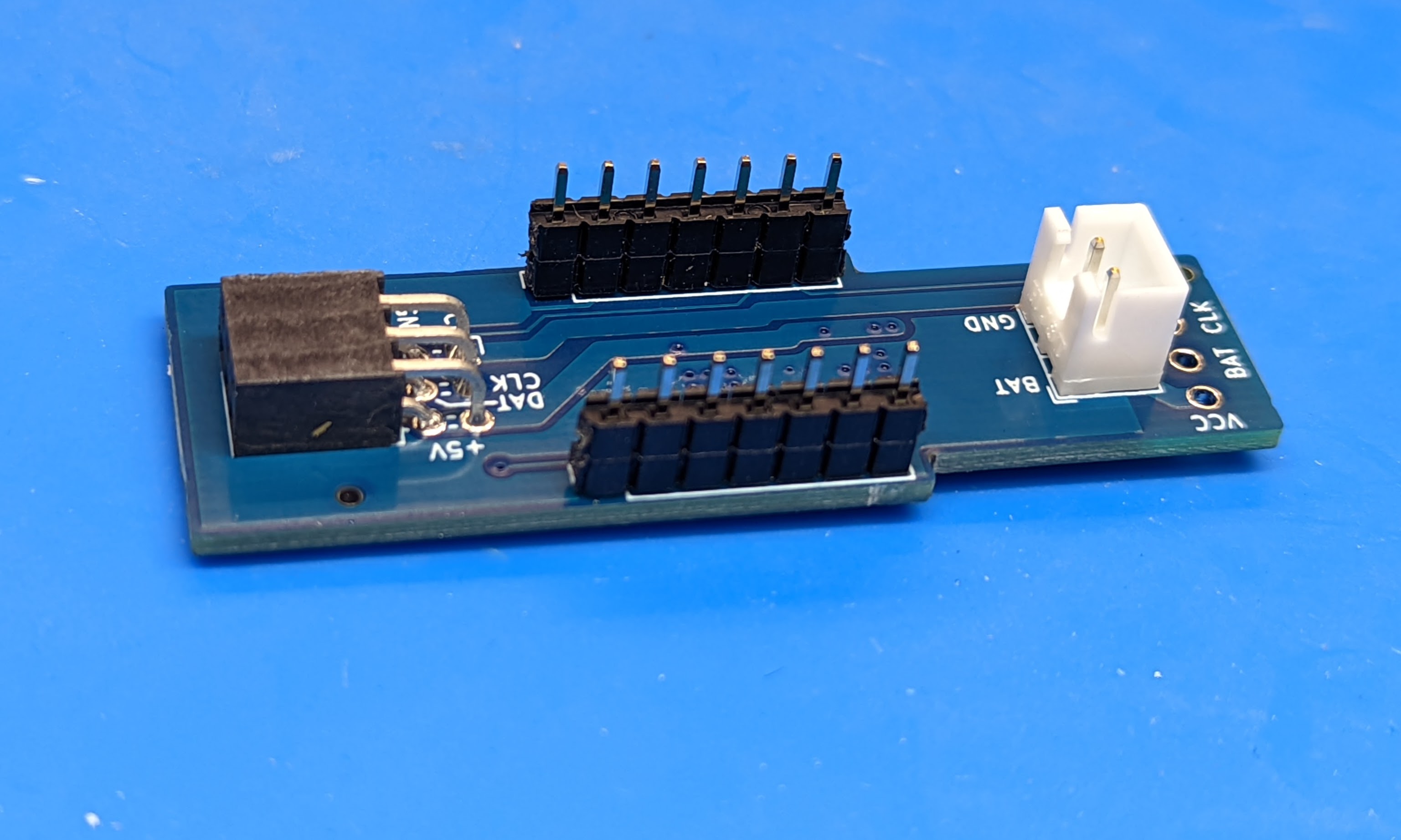
Solder the headers to the custom POV controller shield as shown below. Make sure to solder it on the correct side of the board. The easiest way to keep the headers straight while soldering is to plug them into a breadboard.
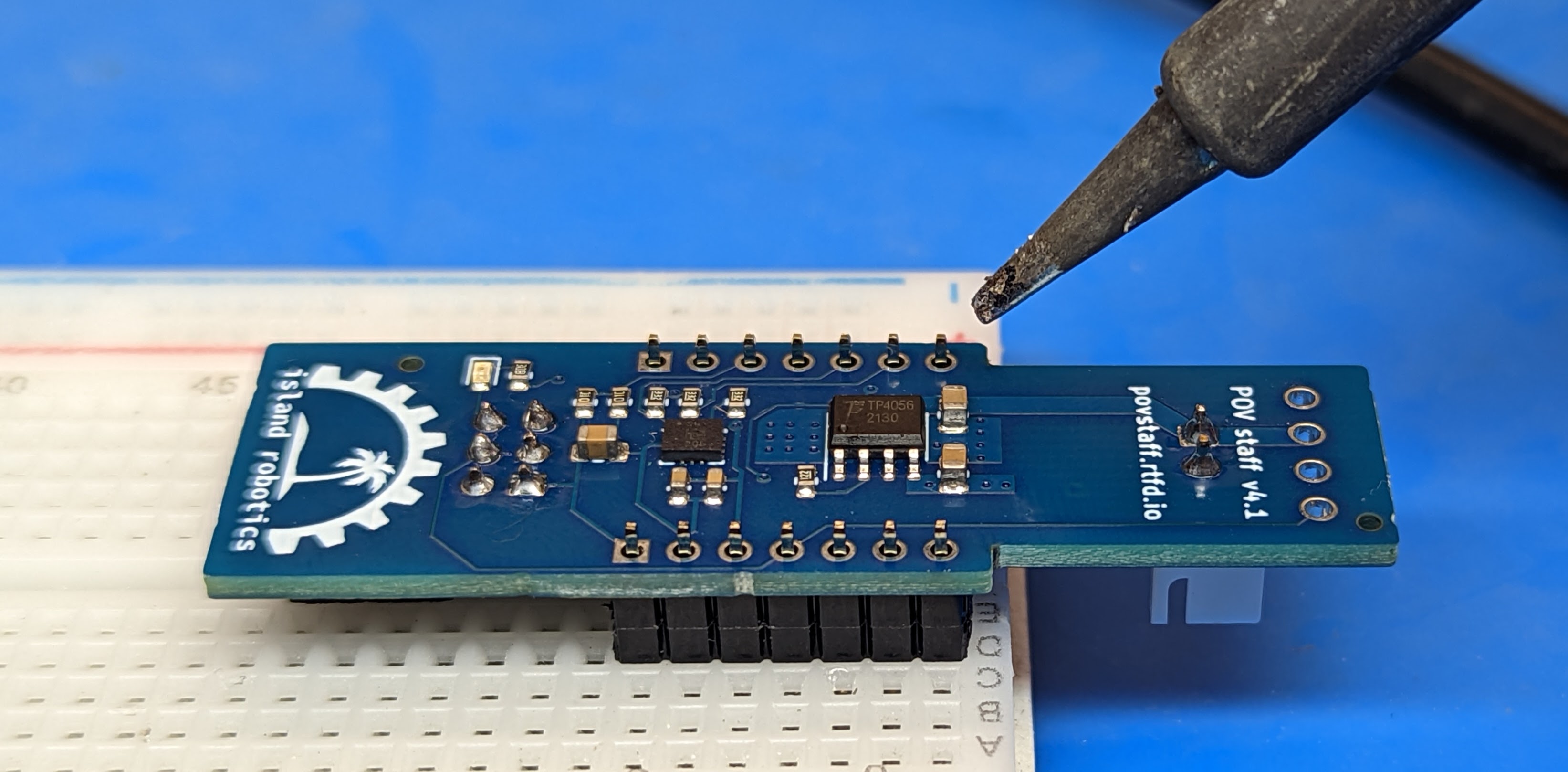
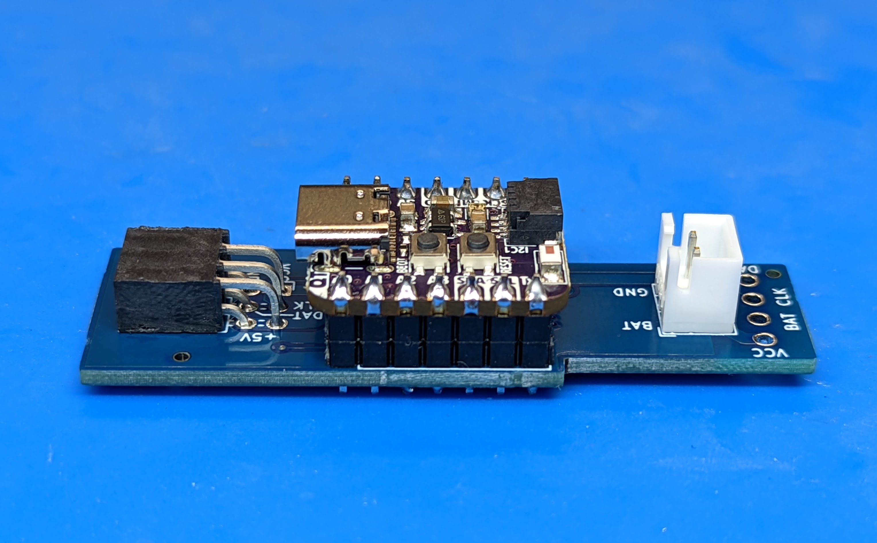
Solder the ESP32-S2 QT Py board to the headers, forming a “sandwich” of two boards as shown in the photos below. Make sure to solder it in the correct orientation: the USB connector should be on top and facing the same way as the black 6-pin header on the controller shield.
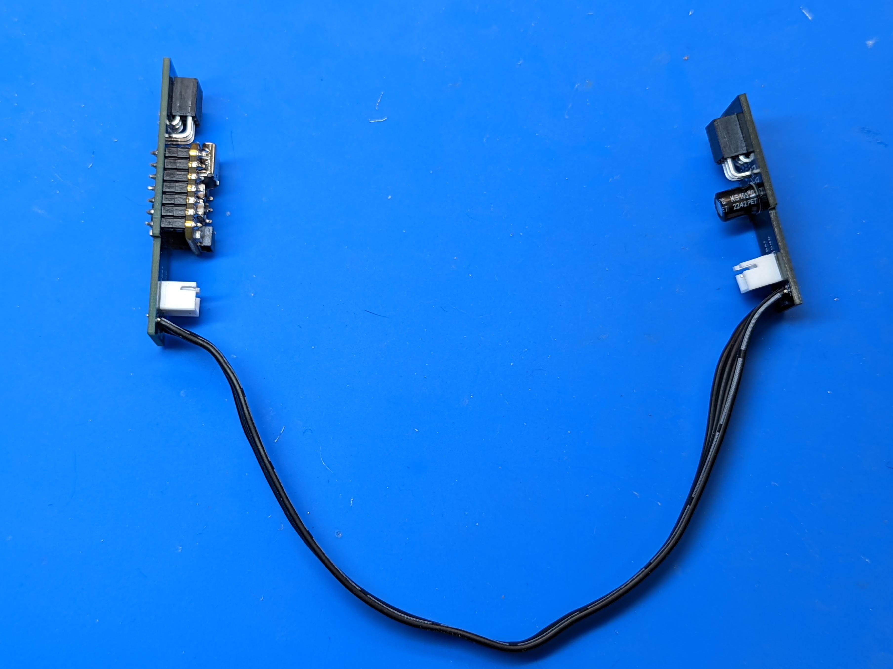
Take the 4-pin wire left over from the previous step and solder it to the controller board on one side and to the switch connector board on the other as shown below. On each board, the wire with white stripe should go into the hole labeled “VCC”.