Step 4: Switch connector
Materials and tools:
Bag C from the kit

Switch
3d printed housing for the switch
2-pin wire (55cm, 20 AWG)
flush cutters, soldering iron
Steps:
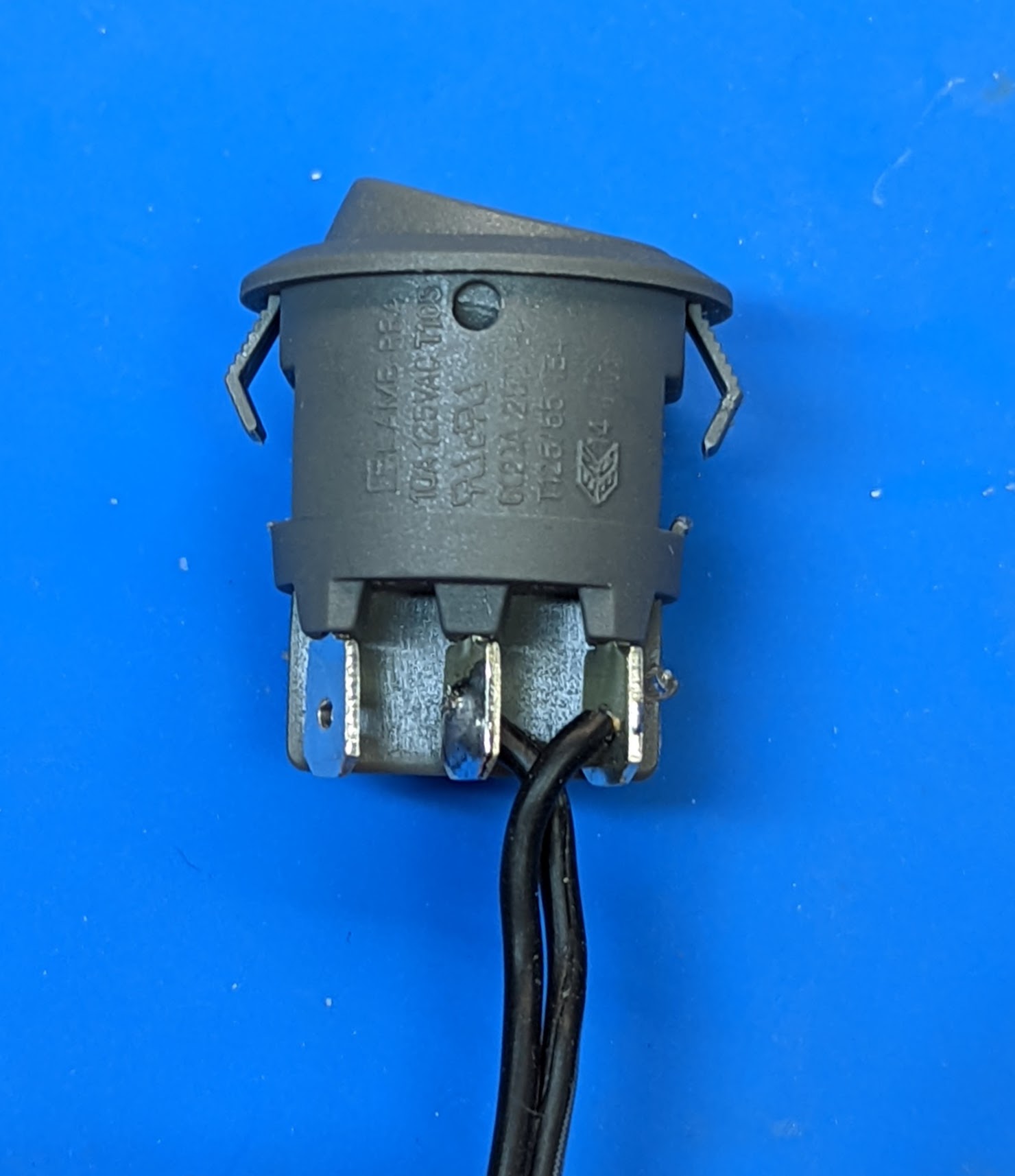
Take the two-pin wire from bag C. Insert the ends of the wire into holes in the switch terminals as shown below. Note: one of the wires must be soldered to the middle terminal, and the other, to one of the other terminals (doesn’t matter which one). It doesn’t matter which of the two wires is soldered to the middle terminal.
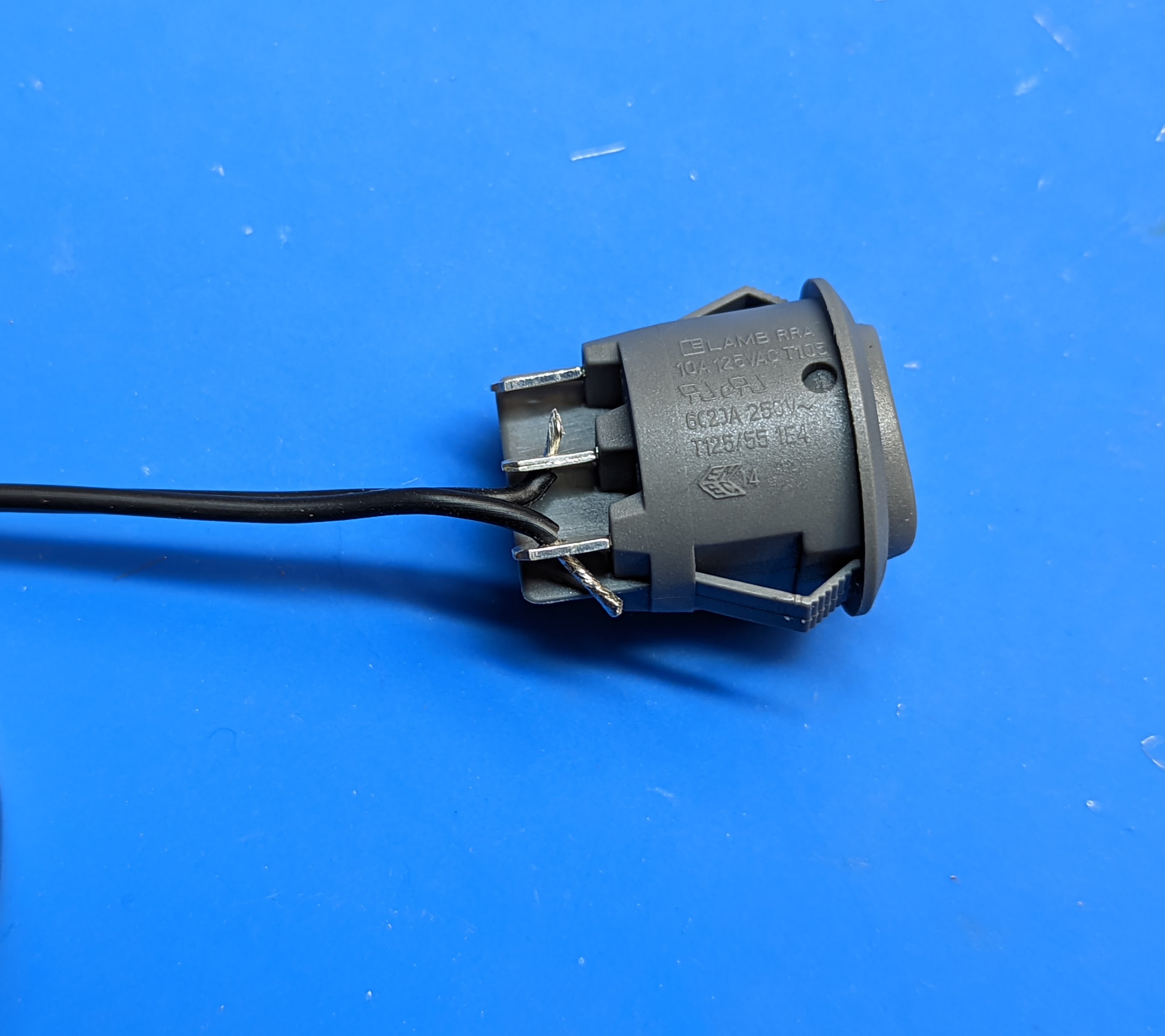
Solder the wires. Use flush cutters to trim the protruding end of the wires.
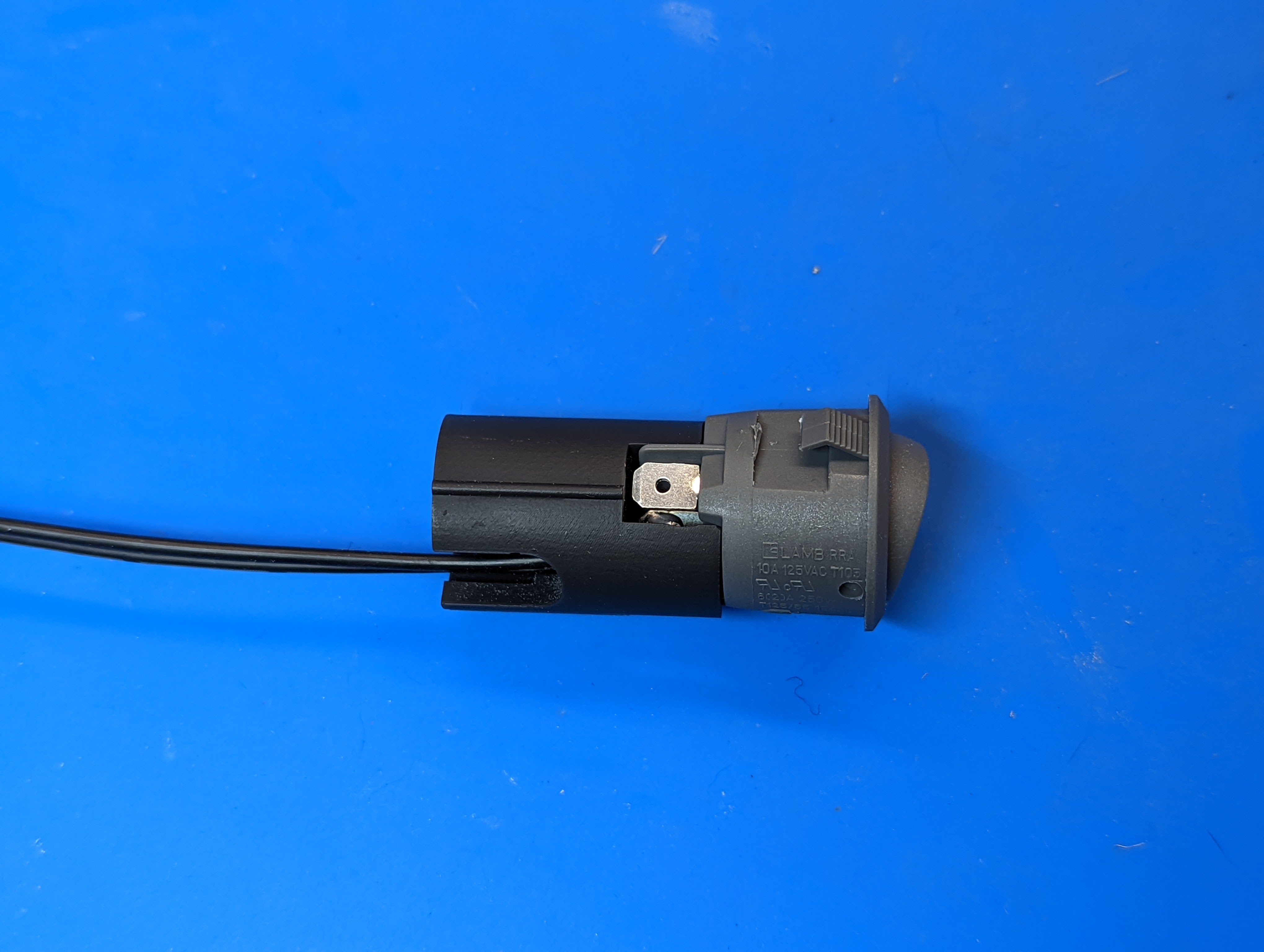
Using flush cutters, cut open the plastic retention tabs on both sides of the switch as shown below. Note: it is recommended to cut it below the “joint”.
Insert the switch in the 3d printed spacer as shown below.
Take the remaining (“SWITCH”) LED assembly, with black PDB. Put the 3d printed spacer with the switch onto the other end of the dowel, making sure that the opening in the spacer is on the same side of the dowel as the two holes in the PDB.
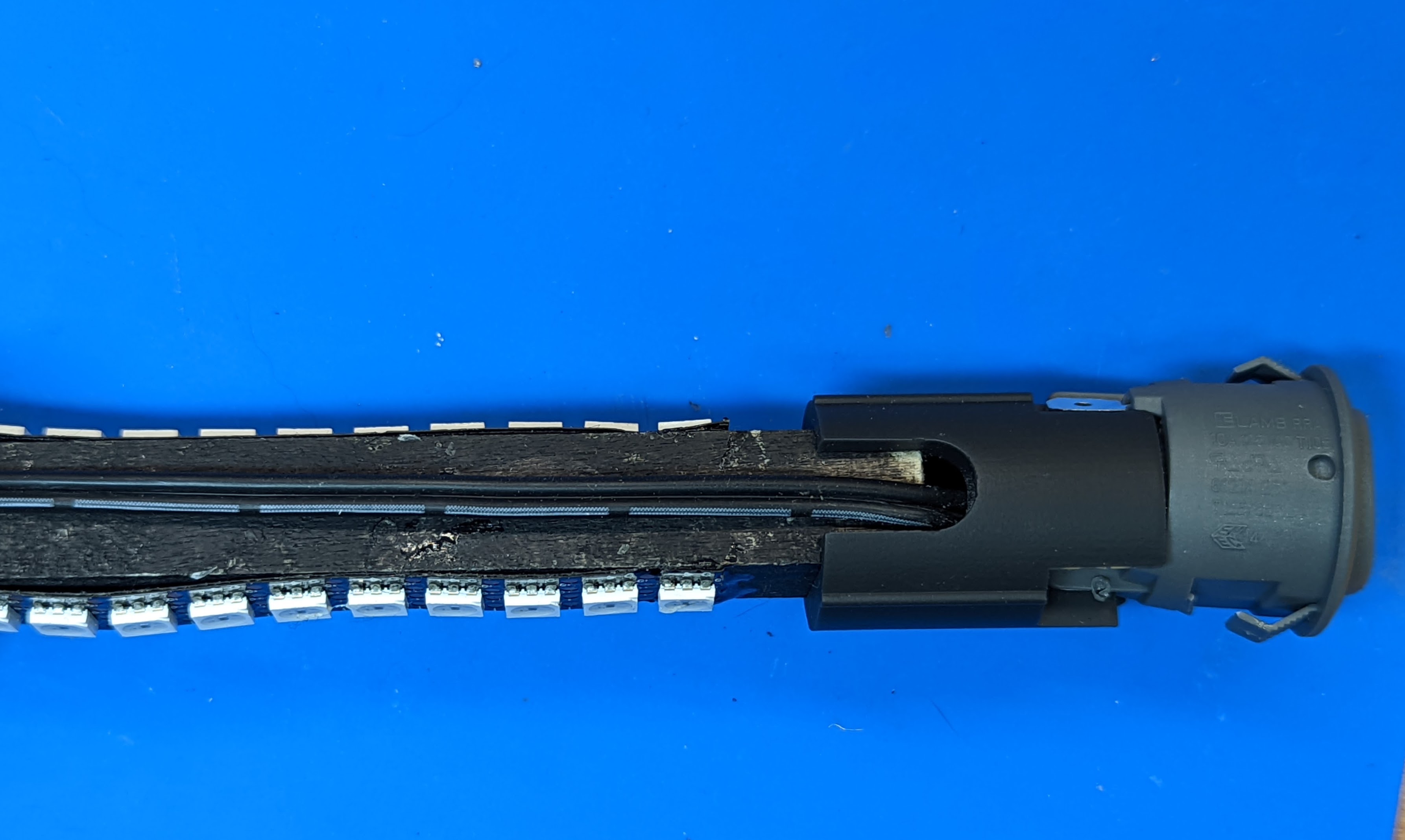
Run the wire along the wood dowel; straighten it to remove twists. Insert the tinned ends of the wire into the holes in the PDB. It doesn’t matter which wire goes into which hole. Solder the wires and use flush cutters to trim the wire ends protruding from on the opposite side of the PDB.