Step 10: Final assembly
Materials:
LED assemblies, from previous steps
battery and controller assembly, from step 9
bag F:
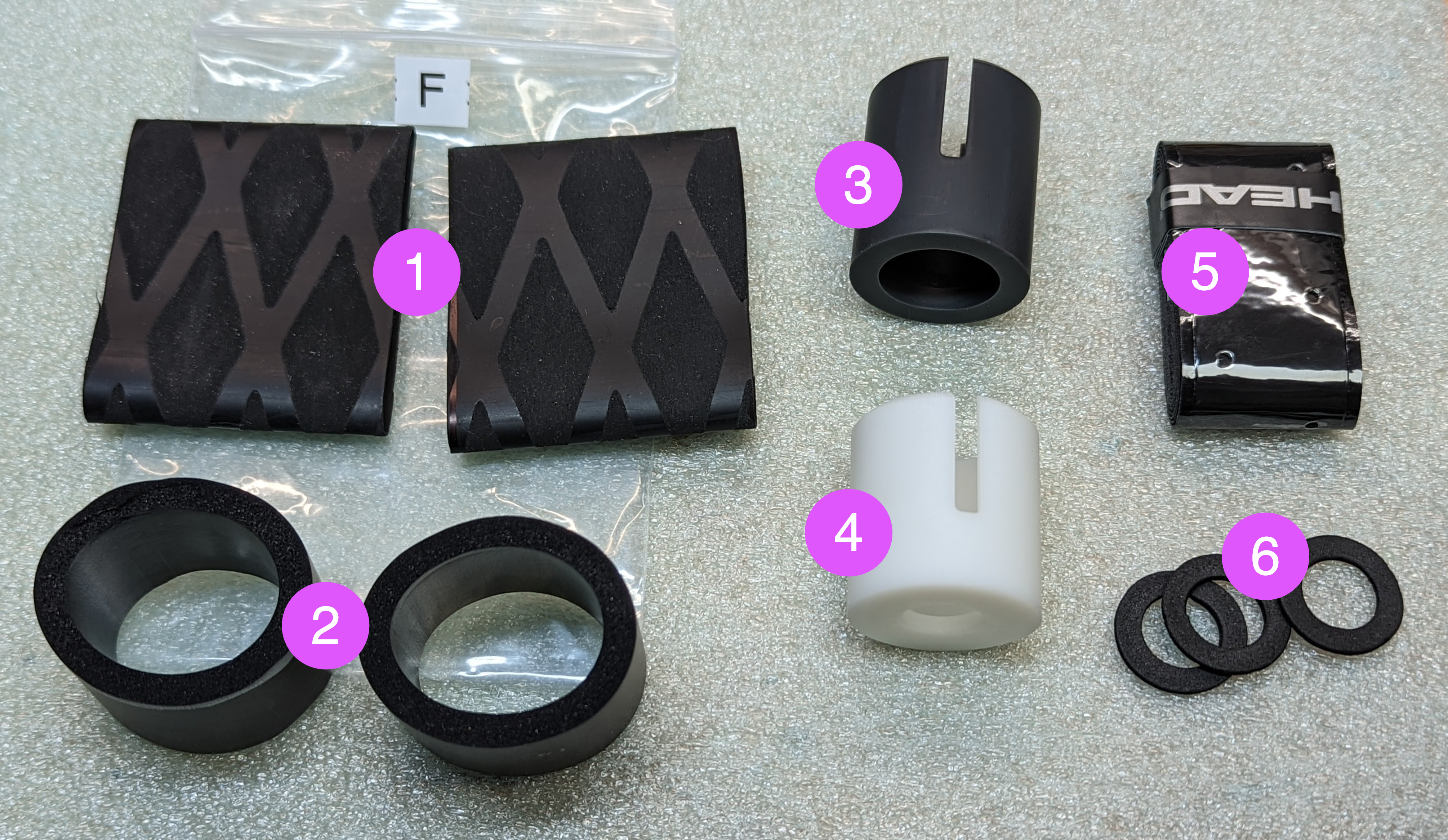
two shrink wrap sleeves
two foam sleeves
Switch end protector
Charge end protector
tennis grip tape
Foam washers
Clear polycarbonate tube (11F/141 cm), from flowtoys.com
Steps:
Make sure you have a large area to work. Lay out the LED assemblies, battery and electronics assembly. Make sure that the switch at the end of SWITCH LED assembly is in middle (OFF) position.
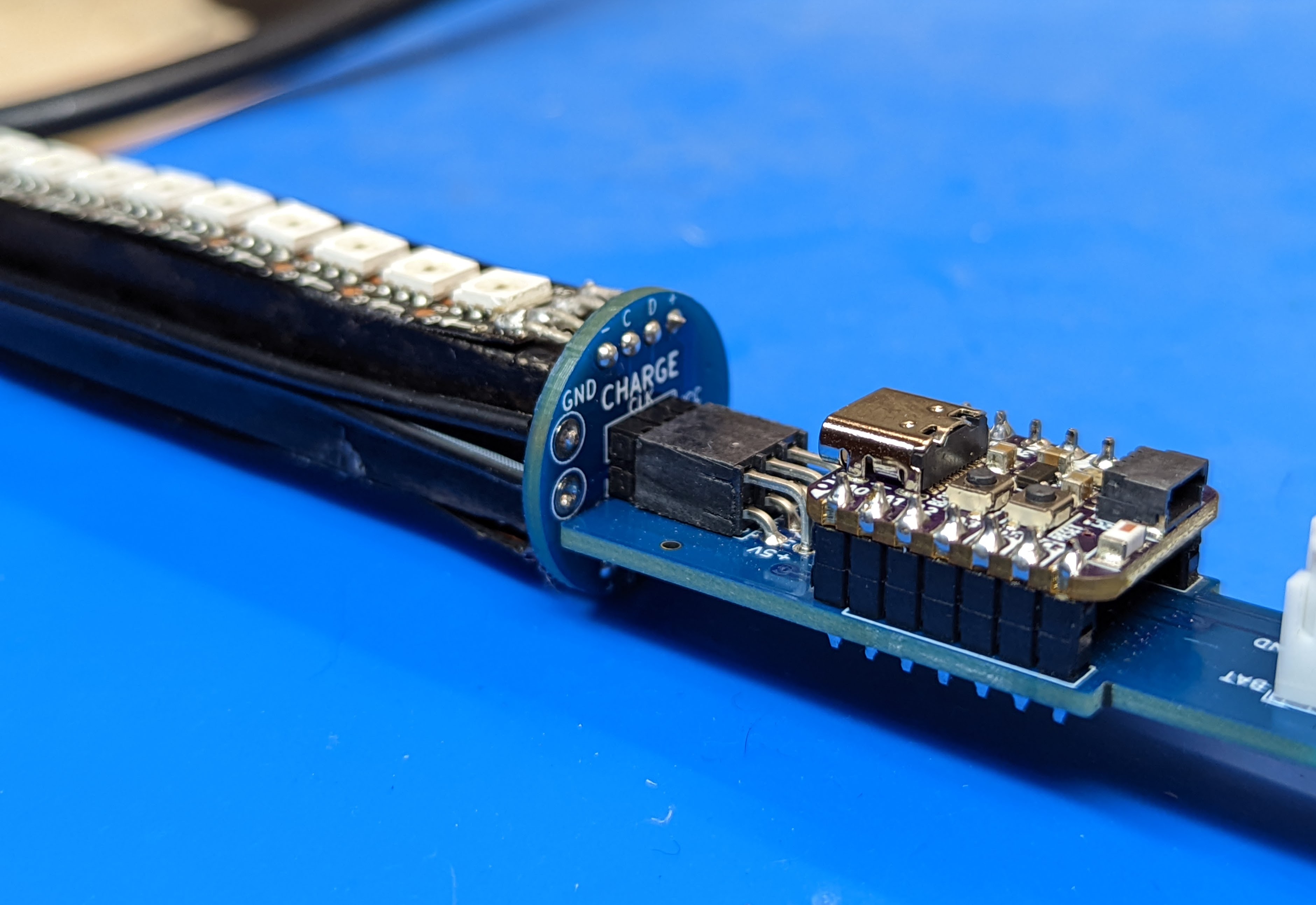
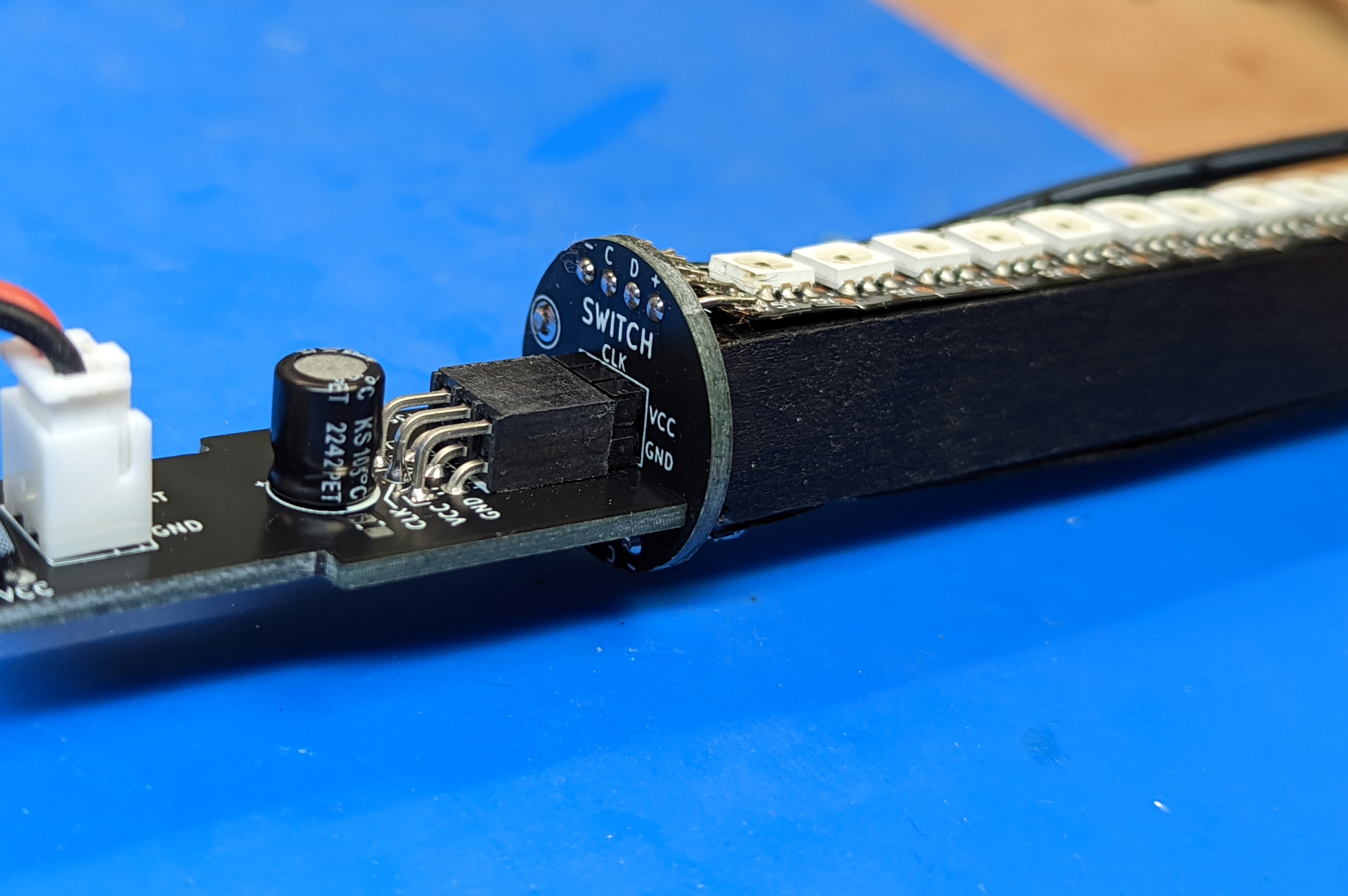
Plug the battery assembly into the LED assemblies. As before, the side which contains QT Py MCU should be plugged into the CHARGE LED assembly, and the other side, into the SWITCH LED assembly. In each case, the board must be plugged into PDB so that the label CHARGE (or SWITCH) should be above the plugged board:
Double-check that everything is plugged correctly. Do the final test: turn the switch on. The LEDs should briefly light up, showing the battery charge. If they don’t, check the troubleshooting section. If everything is OK, turn the switch off and proceed.
Start inserting the whole assembly into the tube, CHARGE end first. Do it slowly. If you meet with resistance, push gently; if it is not enough, do not use excessive force - try to locate the problem. If necessary, remove from the tube and fix the wiring or electric tape. Watch that the LED assembly does not get disconnected from the battery and electronics assembly. Continue until everything is fully in. Push to fully insert the switch; make sure the switch retaining tabs are inside the tube. If everything worked as expected, the charge connector should now be level with the opposite end of the tube or several millimeters inside the tube. In the latter case, use the included foam washers to fill the rest of the tube.
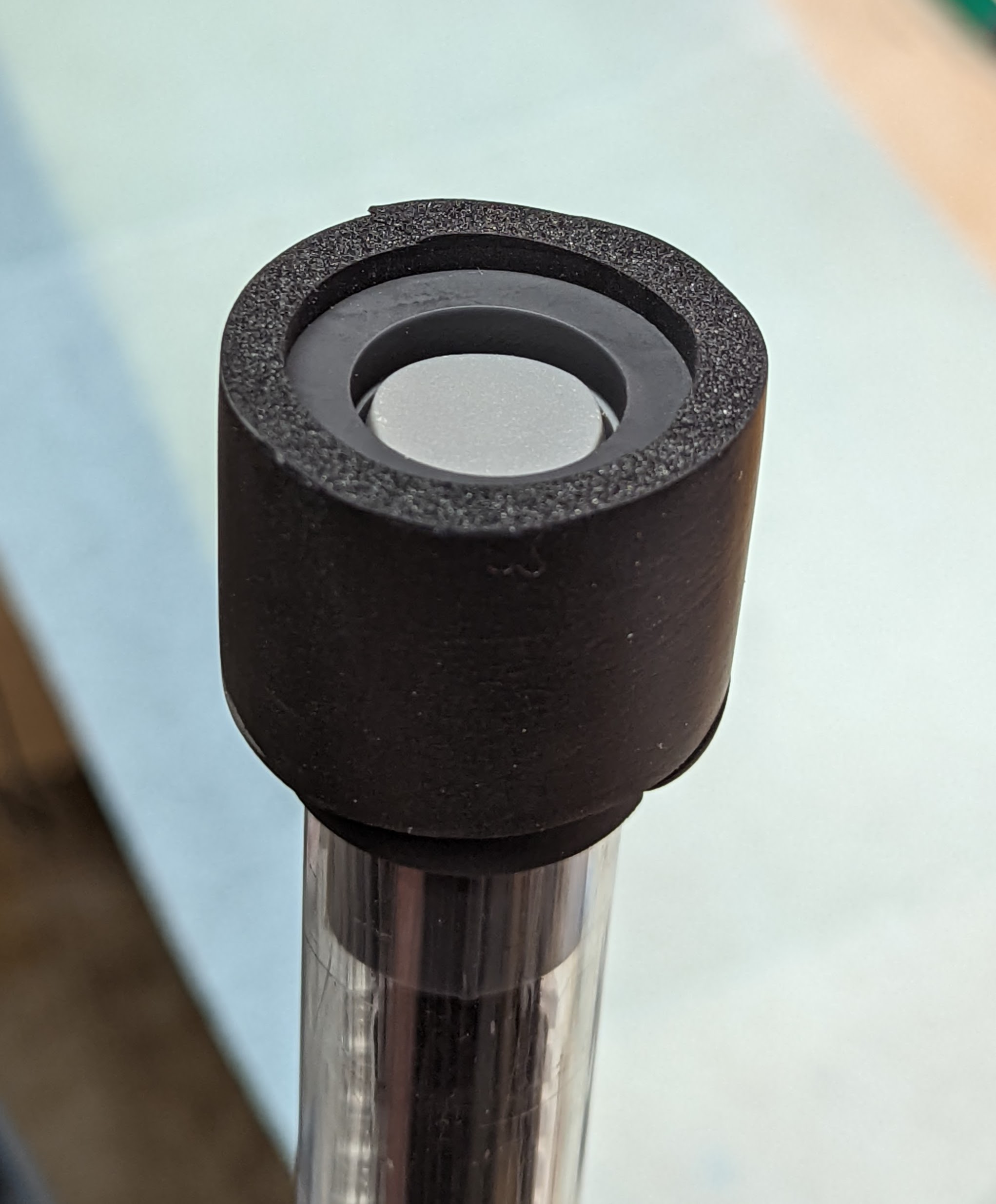
Take the 3d printed switch end protector (item 3 in bag F, the one with larger opening). For shipping, it might have been placed inside the foam wrap; if so, remove it from the foam wrap. Put it over the switch end of tube. There are two small bumps inside the protector which should go into the holes in the tube; if necessary, turn the end protector until you hear the click.
Repeat the same with the charge switch protector (item 4 in the bag), putting it on the opposite end of the tube. Test the whole staff once again, turning it on and off.
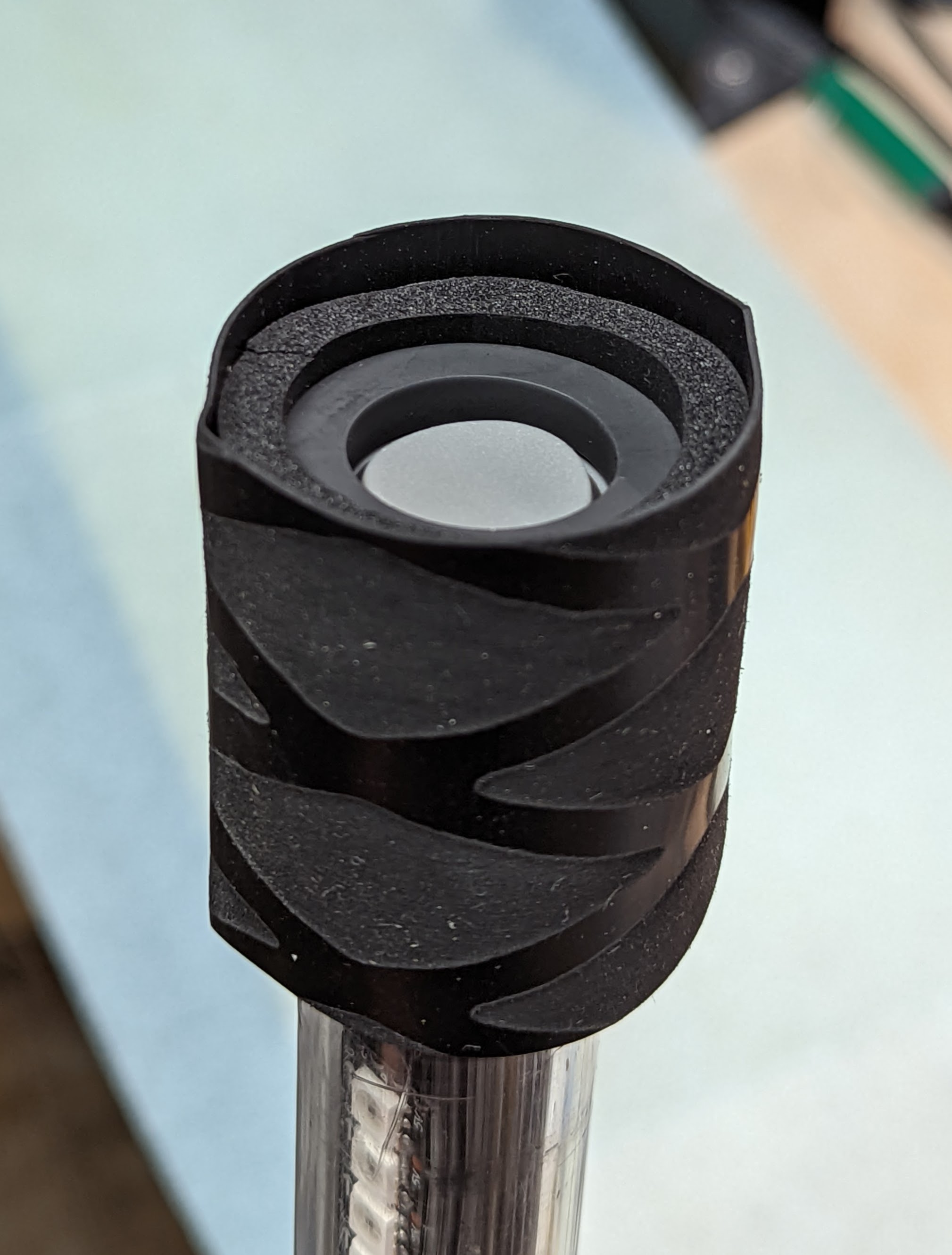
Put the two pieces of the foam tube over the end protectors so that the foam tube extends beyond the protector by 2-3 mm. In 2-3 places, put some epoxy (or crazy glue) between the foam and the 3d-printed end protector.
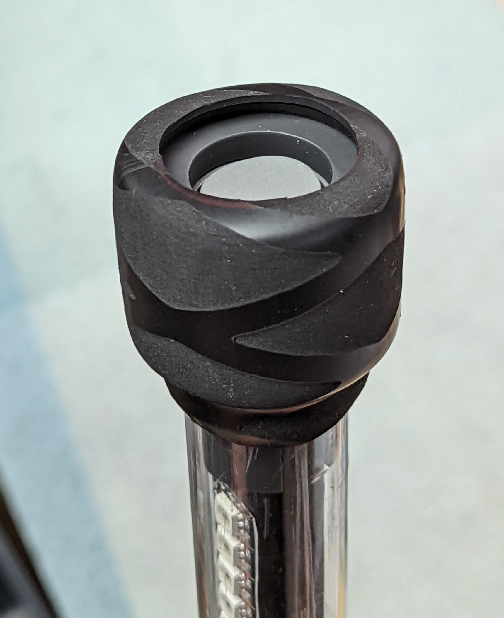
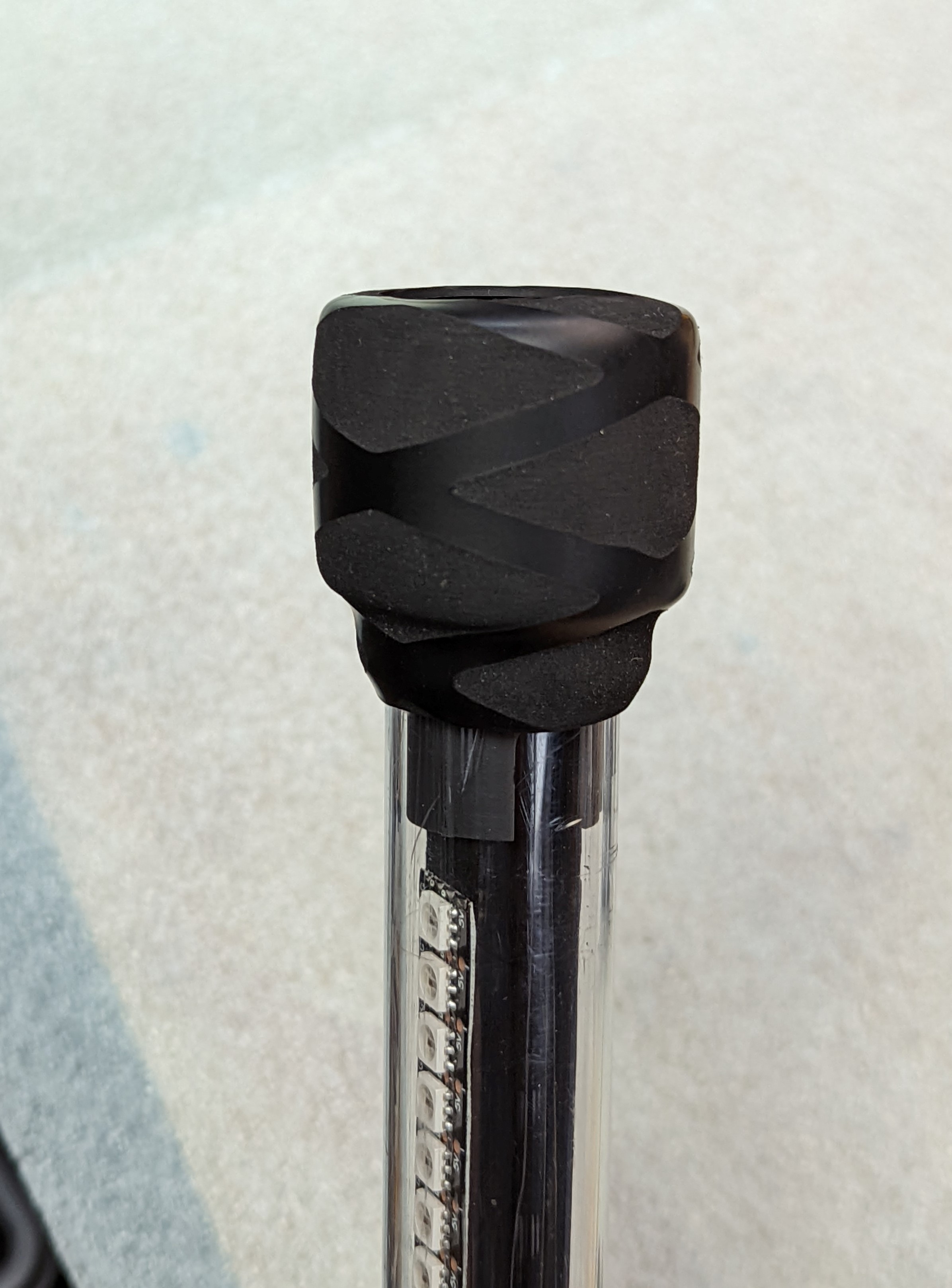
Put the shrink wrap over the foam as shown in the photo below. It should extend beyond the end of the foam wrap by another 5 mm
Use heat gun (on low setting) to shrink the shrink wrap.
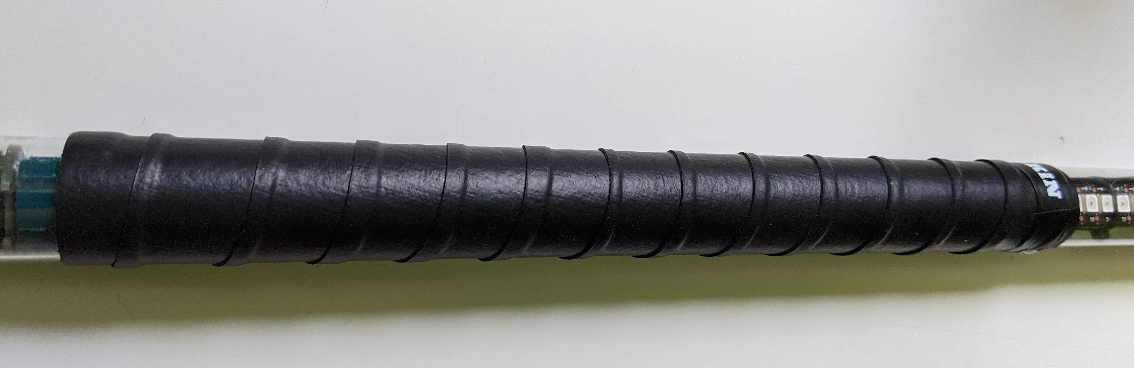
Apply the tennis overgrip tape over the middle part of the tube, containing the battery and electronics assembly - everything between the ends of LED assemblies. You can watch this video to see the proper way of applying the overgrip tape: https://www.youtube.com/watch?v=HNc34XlUBww. Make sure to keep the overlaps between tape turns small - if you make them too large, your tape will run out before you reach the end of battery assembly.
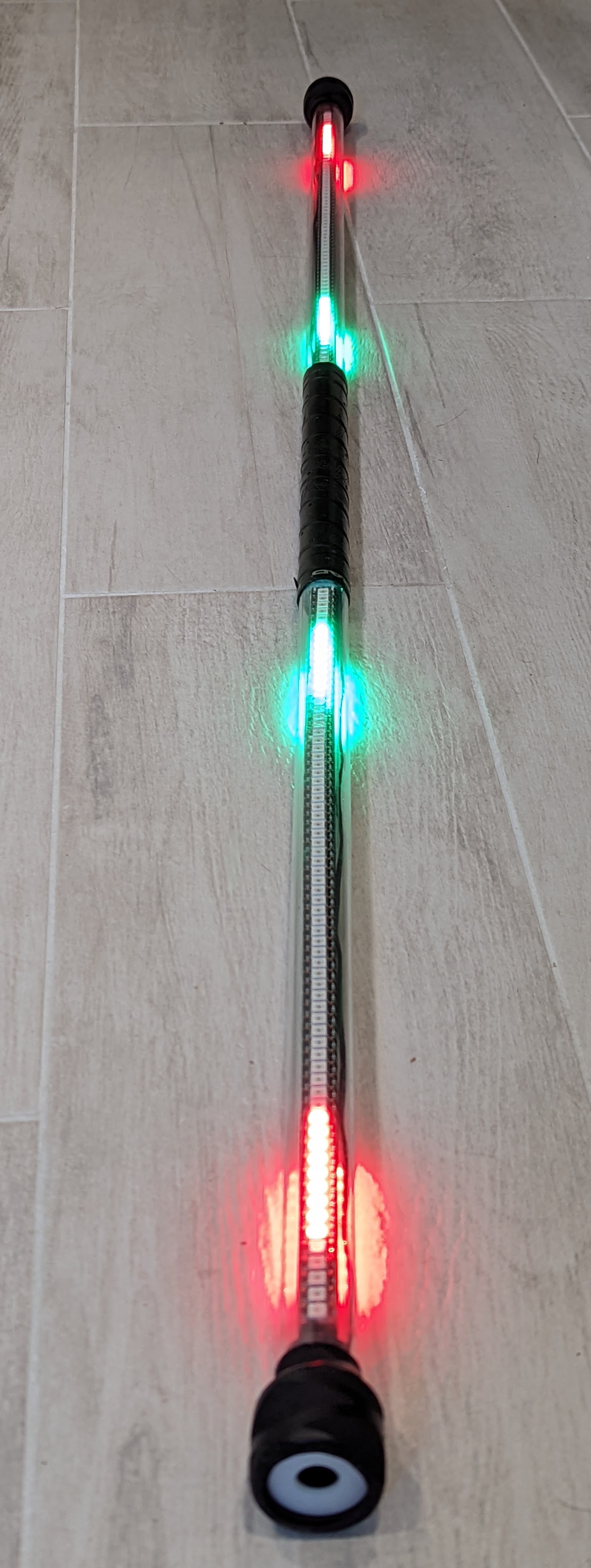
This completes your staff assembly - congratulations!!
Please check the User Guide for instructions on using your staff.