Step 1: Dowels
Materials:
two 1/2” square wood dowels
Bag A from the kit
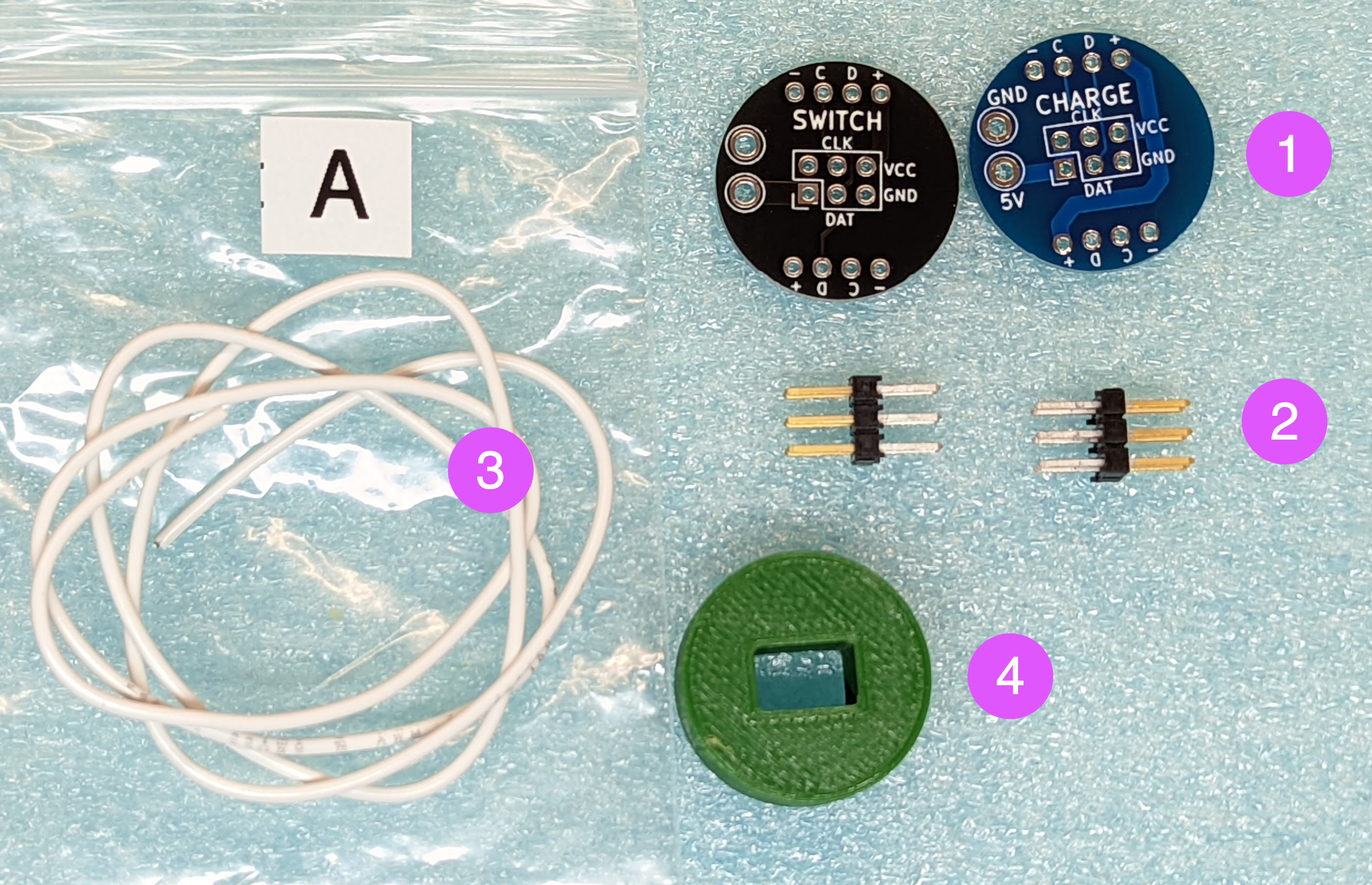
two power distribution boards (PDB),
two 2x3 pin headers (to be soldered to the PDBs)
22AWG solid core wire (to be soldered to LED strips)
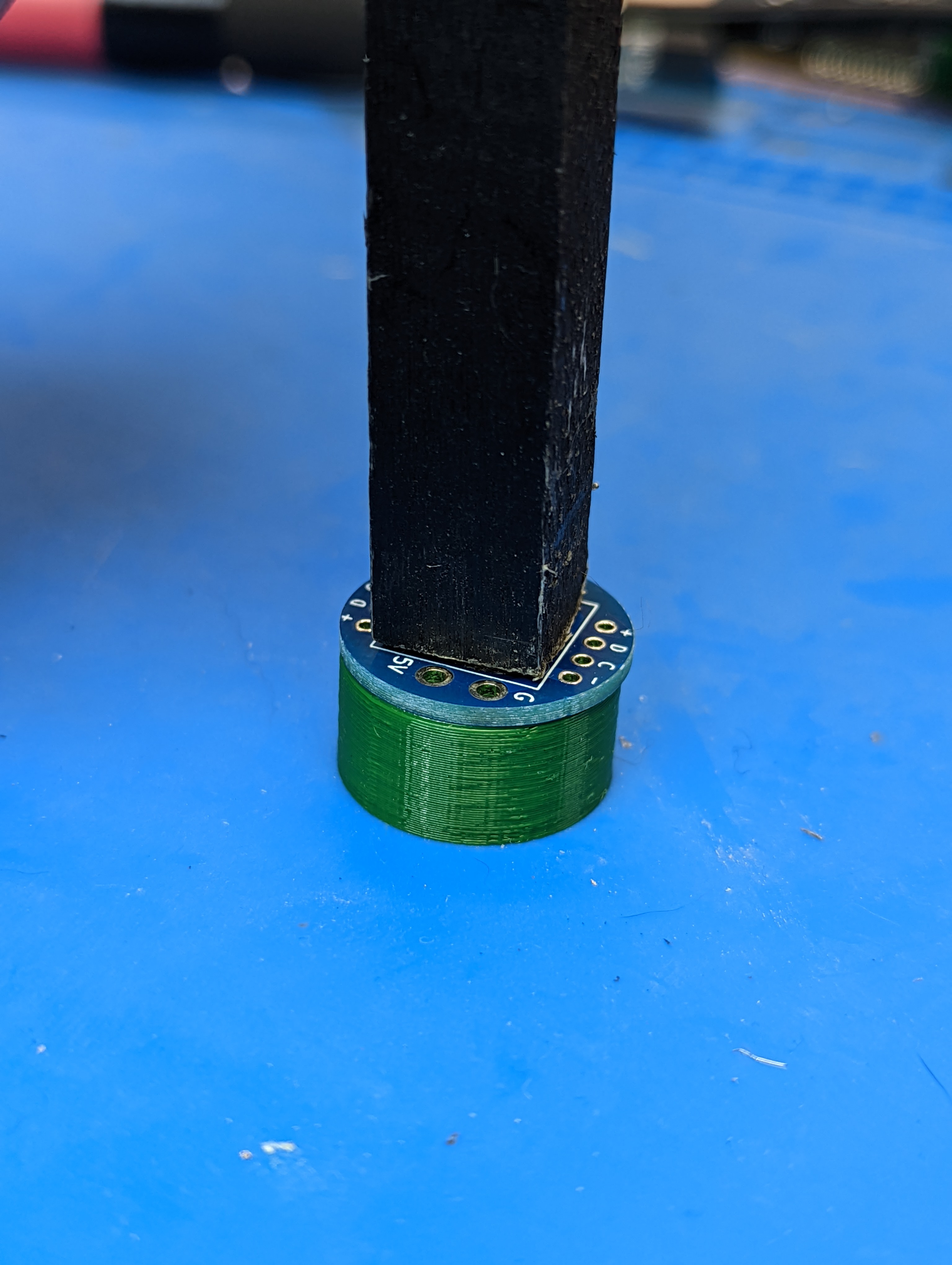
3d printed press tool, to be used for pressing hte PDBs into the dowels. Discard after use
Note: color of the wire and press tool may vary.
Spray paint, epoxy resin.
Steps:
Take the two 1/2” square wood dowels. Use hacksaw to cut each of them to 51.9 cm length; try to keep the cuts square.
Spray paint each of them black. Let dry (you can work on the other steps while the dowels are drying).
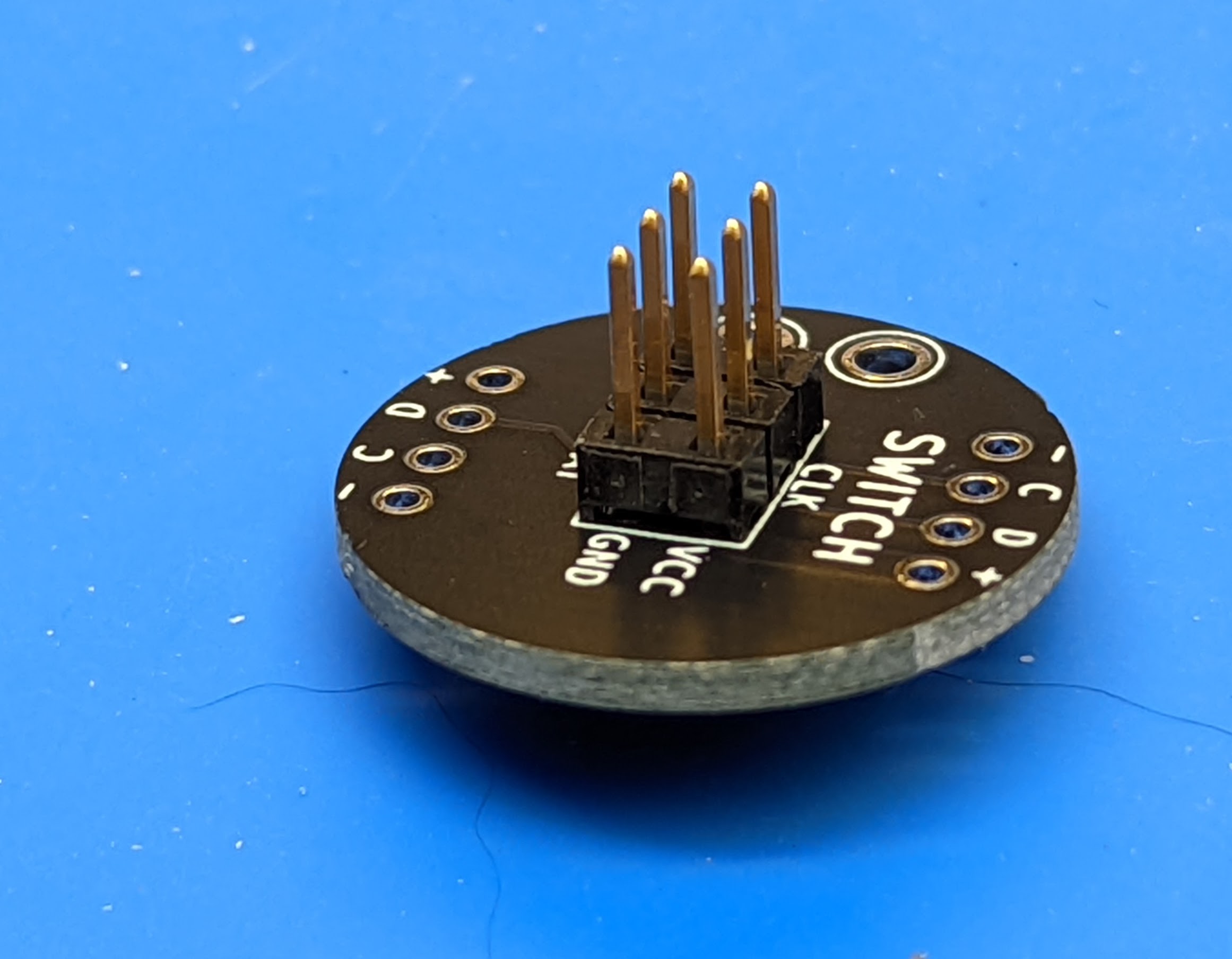
Solder the 2x3 header to each PDB. Make sure to solder it on the correct side: the plastic spacer should be on the side labeled CHARGE (or SWITCH)
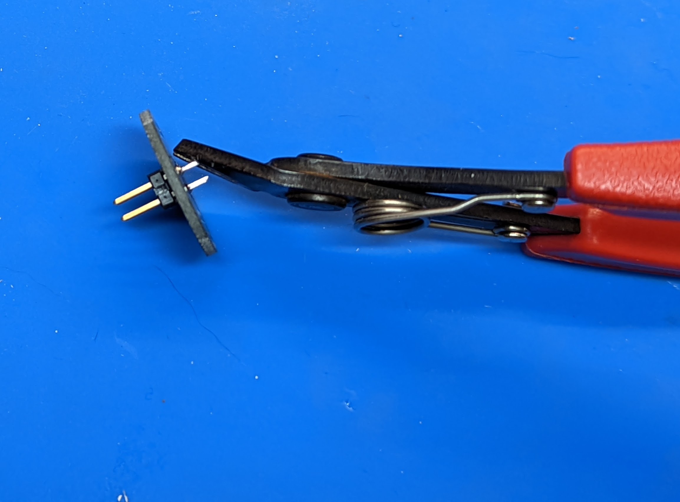
Use flush cutters to trim the 4 corner metal pins on the back side of each PDB, leaving the two middle ones intact:
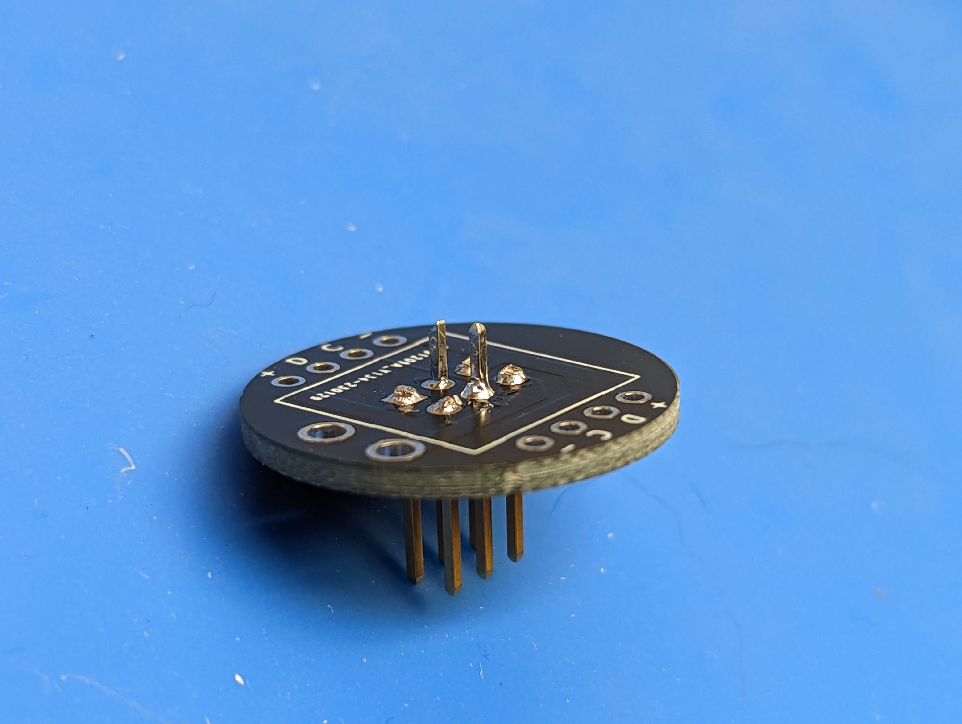
Use the flush cutters to cut about 1 mm off the tip of the two remaining pins on the back at 45 degree angle, creating sharp points.
Press the PDB with soldered headers into the end of the dowel. Use the square drawing on the back for alignment with the dowel. To avoid damaging the header pins, use the included 3d-printed press tool: place it on the table, then the PDB on it (face down), then press the dowel into it. Make sure to press it all the way in: there should be no gap between the dowel and the PDB. Repeat with the other dowel and power distribution board.
Remove the PDB from the dowel. Mix some epoxy glue, apply it to the end of the dowel and replace the PDB seating it fully. Repeat with the second PDB and dowel. Be careful that no epoxy gets on the holes for wires. Leave for an hour to let the epoxy set.
After completing this step, you can discard the 3d printed press tool - you won’t need it any longer.